
LEDs Turning them On and Off
The electronic circuit for controlling LEDs using a reed switch can be designed as follows. The circuit consists of a power source, such as a battery, connected to a series of LEDs. The reed switch is placed in parallel with the LEDs. When the reed switch is in the open state (not activated), the circuit is incomplete, and the LEDs remain off. When a magnet is brought near the reed switch, the internal contacts close, completing the circuit and allowing current to flow through the LEDs, illuminating them.
For a more advanced configuration, a latching reed switch can be utilized. In this case, the circuit design remains similar, but the latching mechanism allows the LEDs to stay on even after the magnet is removed. This can be achieved by using a latching reed switch that maintains the closed state until the opposite pole of a magnet is brought near, which will open the circuit.
Additionally, it is advisable to include current-limiting resistors in series with the LEDs to prevent excessive current flow that could damage the LEDs. The resistor value can be calculated based on the LED specifications, including forward voltage and current ratings.
The overall design should also consider the placement of the reed switch and magnet to ensure reliable operation. Proper housing for the components can help protect the fragile reed switches from physical damage during operation. Furthermore, the circuit can be integrated with other components, such as microcontrollers, for more complex control options, including remote operation or integration with other model railroad systems.The last installment in this series ( LEDs 102 - Use On Board Trains ) ended with a few thoughts about turning battery powered LEDs on and off. In this article I would like to explore several options for turning LEDs, and other things on your railroad, on and off.
A simple on/off toggle switch meets the first and last requirement and, depending on where you put it, the other two as well. I have mounted small toggle switches under cars and tenders to do a variety of things and find them to be a good solution so long as I can remember where they are located under the car! The switch pictured here is inside of a tool box on a tender. A reed switch is a magnetically activated switch that is frequently used in model railroad applications.
They are also commonly used to trigger burglar alarms when a window or door is opened. Most are composed of a small glass tube that contains two small magnetized contacts that normally do not touch. This makes most reed switches Normally Open, sometimes referred to as NO as opposed to NC switches which are Normally Closed.
When a magnet is brought near the switch the two contacts come together and the switch closes. When the magnet is removed the contacts spring apart and the circuit opens. If you would like more information on reed switches they were covered in some detail in my article Garden Railway Sensors - Part 1 As I mentioned in the last article you can use one of these common reed switches to turn LEDs on and off by gluing the reed switch to the inside of the roof of a car. Placing a small magnet on the top of the car will turn the LEDs on and they will go off when it is removed.
As you can imagine this presents a few problems. You have to find a place where the magnet is not likely to fall off as the train moves around the railroad and then you have to disguise the magnet as something that belongs on top of a car. With the likelihood of losing magnets approaching 100% when used in this manner we may want to rethink this option!
A latching reed switch, that is a reed switch that latches on and stays on even with the magnet removed, would be an ideal solution. In LEDs 102 you may recall that I briefly mentioned that latching reed switches were something of a rare commodity.
Since then I came upon a supplier for latching reed switches on eBay. I ordered half a dozen (at $1. 50 each plus shipping) for experimentation. The good news is that they do work as advertised. The bad news is that I broke the first three that I used during testing and expect at least one or two more to bite the dust in the near future! It turns out that these reed switches are extremely fragile. I broke one by dropping it a short distance onto a carpeted floor. Another broke as soon as I put alligator clips directly onto the contacts for testing. The stress on the glass was too much for it. By then I knew that there was a problem. I soldered flexible wires to the contacts on the third switch and glued its glass cylinder to a piece of wood for testing.
One of its contacts pulled right out of the glass body of the switch within a few hours of testing. To say the least these are the touchiest reed switches I have ever seen. On a more positive note they do work as expected. If you bring one pole of a permanent magnet near the reed switch the contacts within the glass tube come together and current flows. If you carefully remove the magnet the contacts will stay together and your LEDs or whatever is connected to the switch will stay on.
To turn the switch off turn the magnet over and bring the other pole near the switch. The contacts will relax and separate breaking the circuit. Their operation is not completely flawless. I found that the switches sometimes turned off as I removed the magnet that was supposed to turn them on. Taking two or three tries to turn the LEDs on or off was an irritation but not a major problem. No current handling specifications were 🔗 External reference
Related Circuits
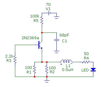
This article presents basic circuits for pulsing infrared LEDs and low-power visible semiconductor lasers utilizing inexpensive and readily available components. Numerous interesting and practical applications are referenced, alongside several online resources. The focus of the article is on the...
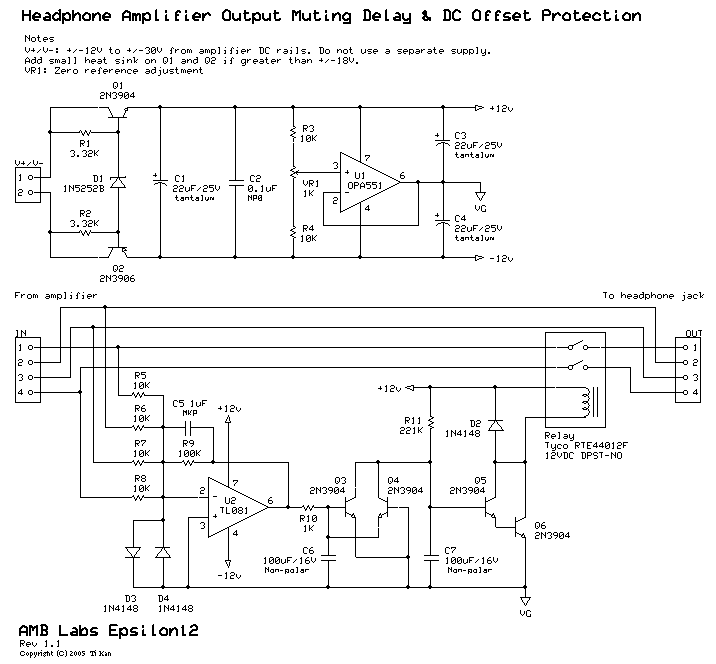
A low-pass filter is a stable state-space system that has an input and produces an output. If the input is a quasi-periodic signal, the output will be the same quasi-periodic signal with a phase shift. The key difference is...
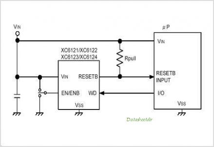
The XC61H series is a highly accurate, low power consumption CMOS voltage detector featuring a delay circuit. The detection voltage maintains high accuracy with minimal temperature drift. Output configurations are available in both CMOS and N-channel open drain. As...
An ordinary automatic room power control circuit has only one light sensor. So when a person enters the room it gets one pulse and the lights come on. When the person goes out it gets another pulse and the...
The widely used 555 timer is utilized in a bistable configuration that employs a simple push-button for a push-on, push-off action. This configuration operates on the principle of maintaining a stored charge in a capacitor, which manipulates a Schmitt...
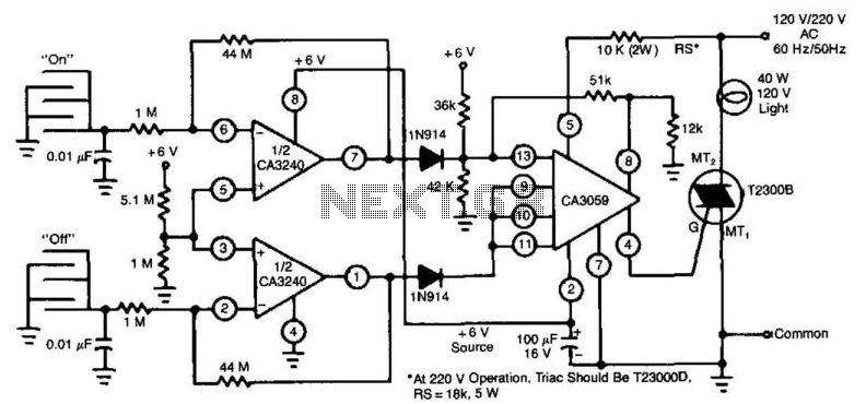
This circuit employs a CA3240 dual BiMOS operational amplifier to detect small currents that flow between the contact points on a touch plate. The high input impedance of the CA3240 enables the use of 1-megaohm resistors in series with...