
Electronic amplifier

Amplifiers serve critical roles in various electronic systems, transforming weak signals into stronger, more usable forms. The design of an amplifier encompasses numerous considerations, including linearity, bandwidth, and distortion characteristics. Linearity is paramount; it ensures that the amplifier faithfully reproduces the input signal without introducing unwanted artifacts. Bandwidth defines the frequency range over which the amplifier operates effectively. Distortion can arise from non-linear operating conditions, where the output deviates from the input signal shape, leading to potential signal integrity issues.
In practice, amplifiers are often categorized into different classes based on their operation and efficiency, such as Class A, Class B, Class AB, and Class D. Each class has distinct characteristics regarding linearity, efficiency, and thermal performance, influencing the choice of amplifier for specific applications. For instance, Class A amplifiers are known for their high linearity and low distortion but suffer from poor efficiency, while Class D amplifiers offer high efficiency and compact size, making them suitable for battery-operated devices.
Furthermore, feedback mechanisms are frequently employed in amplifier design to enhance stability and linearity. Negative feedback reduces gain but improves bandwidth and linearity, while positive feedback can increase gain but may lead to instability if not carefully managed. The choice of feedback topology, whether voltage or current feedback, also impacts the amplifier's performance and application suitability.
In summary, amplifiers are vital components in the realm of electronics, with their design and classification deeply rooted in the interplay between input and output characteristics, impedance matching, and the specific requirements of the application at hand. Understanding these factors is essential for engineers and designers to create effective amplification solutions tailored to diverse electronic systems.The term amplifier as used in this article can mean either a circuit (or stage) using a single active device or a complete system such as a packaged audio hi-fi amplifier. An electronic amplifier is a device for increasing the power of a signal. It does this by taking energy from a power supply and controlling the output to match the input signal shape but with a larger amplitude. In this sense, an amplifier may be considered as modulating the output of the power supply. Amplifiers can be specified according to their input and output properties. [1] They have some kind of gain, or multiplication factor relating the magnitude of the output signal to the input signal. The gain may be specified as the ratio of output voltage to input voltage ( voltage gain ), output power to input power ( power gain ), or some combination of current, voltage and power.
In many cases, with input and output in the same units, gain will be unitless (although often expressed in decibels ); for others this is not necessarily so. For example, a transconductance amplifier has a gain with units of conductance (output current per input voltage).
The power gain of an amplifier depends on the source and load impedances used as well as its voltage gain; while an RF amplifier may have its impedances optimized for power transfer, audio and instrumentation amplifiers are normally employed with amplifier input and output impedances optimized for least loading and highest quality. So an amplifier that is said to have a gain of 20dB might have a voltage gain of ten times and an available power gain of much more than 20dB (100 times power ratio), yet be delivering a much lower power gain if, for example, the input is a 600 ohm microphone and the output is a 47 kilohm power amplifier`s input socket.
In most cases an amplifier should be linear; that is, the gain should be constant for any combination of input and output signal. If the gain is not constant, e. g. , by clipping the output signal at the limits of its capabilities, the output signal will be distorted.
There are however cases where variable gain is useful. There are many alternative classifications that address different aspects of amplifier designs, and they all express some particular perspective relating the design parameters to the objectives of the circuit. Amplifier design is always a compromise of numerous factors, such as cost, power consumption, real-world device imperfections, and a multitude of performance specifications.
Below are several different approaches to classification: Electronic amplifiers use two variables: current and voltage. Either can be used as input, and either as output leading to four types of amplifiers. In idealized form they are represented by each of the four types of dependent source used in linear analysis, as shown in the figure, namely: In practice the ideal impedances are only approximated.
For any particular circuit, a small-signal analysis often is used to find the impedance actually achieved. A small-signal AC test current Ix is applied to the input or output node, all external sources are set to AC zero, and the corresponding alternating voltage Vx across the test current source determines the impedance seen at that node as R = Vx / Ix.
Amplifiers designed to attach to a transmission line at input and/or output, especially RF amplifiers, do not fit into this classification approach. Rather than dealing with voltage or current individually, they ideally couple with an input and/or output impedance matched to the transmission line impedance, that is, match ratios of voltage to current.
Many real RF amplifiers come close to this ideal. Although, for a given appropriate source and load impedance, RF amplif 🔗 External reference
Related Circuits
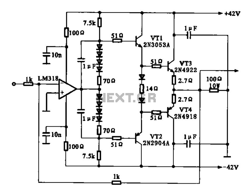
The current amplifier circuit configuration is illustrated in the figure. It consists of a two-stage operational amplifier, the LM318, arranged in a complementary push-pull amplifier configuration, which exhibits low output resistance and possesses load capacity features. The current amplifier circuit...
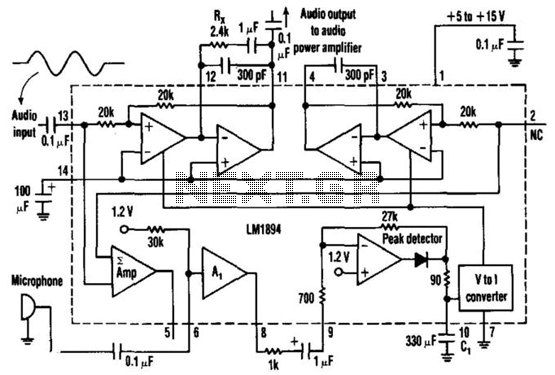
This single-chip circuit adjusts its audio gain according to the ambient noise picked up by the microphone. When operating in a quiet environment, the audio output is quiet, while a noisy environment results in a louder audio output. Audio...
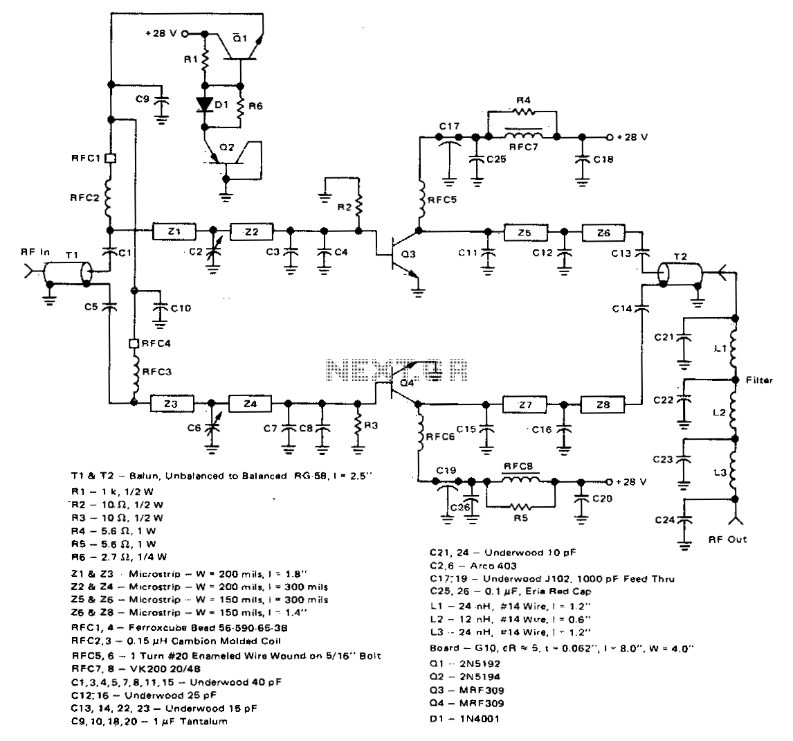
This 100-watt linear amplifier can be built using two MRF309 transistors in a push-pull configuration, requiring only 16 watts of drive power within the frequency range of 420 to 450 MHz. It operates from a 28-volt supply and achieves...
This FM RF power amplifier circuit is constructed using a BLY94 transistor, which can deliver up to 50W at a frequency of 175MHz with a power gain of 7dB, resulting in approximately 5 times power amplification. However, in this...

A practical amplifier circuit. An electronic amplifier is a device that increases the power of a signal. It accomplishes this by drawing energy from a power supply and adjusting the output to correspond to the input signal shape, albeit...

The input capacitor is used for low-frequency cut-off, with a standard value of 0.1 µF, resulting in a cut-off frequency of approximately 16 Hz. The input capacitor plays a critical role in electronic circuits, particularly in signal processing and audio...