
1984 F-350: crew cab My fuel gage switch in the dash

The described circuit involves a fuel pump relay system for a 1984 F-350 crew cab equipped with a 460 engine. The circuit's main components include the fuel tank selector switch, the fuel pump relay, and the fuel pumps for both the front and rear tanks. The fuel tank selector switch, located on the dashboard, allows the driver to choose between the front and rear fuel tanks. This switch sends a signal to the relay, which controls the power flow to the selected fuel pump.
The relay serves a critical role in this circuit. When the switch is activated, it should energize the relay, allowing current to flow to the appropriate fuel pump. The relay receives power from the battery and is grounded to complete the circuit. The correct operation of the relay is essential for the fuel pump to function. The presence of power at the relay's input pins indicates that the signal from the dashboard switch is being received.
The troubleshooting process involves verifying the power supply to the relay and ensuring the relay itself is functioning correctly. It is essential to check the connections, including the red wire leading to the front tank pump and the brown with white and pink with black wires, to confirm that the relay is being energized. The presence of two brown with white wires can lead to confusion; therefore, it is crucial to identify which wire corresponds to the switched power from the dashboard and which one is the output to the rear tank.
In summary, effective troubleshooting of the fuel system in the 1984 F-350 requires careful examination of the wiring, relay functionality, and switch operation. Proper identification of the circuit components and their interconnections will aid in resolving the issue of the non-functioning fuel gauge and pump.A 1984 F-350 crew cab w/a 460. My fuel gage does not work and it will not pump from the front tank, were do I start I have replaced the switch in the dash and the switch on the frame. I just turned it on and did not hear anything. The pigtail that goes into the frame pump has power to all the pins with the switch in the cab on the front tank.
With it on the rear tank the end pin(by the blank hole) is not on. I will gladly increase the payment if you can get this fixed for me. I will check this and get back to you when I get home from work this evening. Sorry it took so long, I check both wires and they both have power with and without the ignition on. You did something wrong. You have just verified all the inputs to the relay and replaced the relay itself and it still doesn`t work. Something is wrong with your tests. Then I will go back and recheck everything that I have done. To make sure that I checked the right wires these are the ones I check: The red wire to the tank pump, coming into at the top of the tank.
The ones you mentioned to the relay, and the ground. Correct With the key on and the switch on front tank, you should have power on the brown with white and the pink with black and ground on the Black wire. With all this, the relay should energize and power the red wire going to the front tank I am going to interject because I looked at the diagram and there are TWO Brn/W wires going to the relay.
One is the switched power from the dash selector (the one you`re looking for power at), the other is the relay output to the REAR tank (the one you already know is working). You may be checking for power at the wrong one. Ask-a-doc Web sites: If you`ve got a quick question, you can try to get an answer from sites that say they have various specialists on hand to give quick answers.
Justanswer. com. Traffic on JustAnswer rose 14 percent. and had nearly 400, 000 page views in 30 days. inquiries related to stress, high blood pressure, drinking and heart pain jumped 33 percent. 🔗 External reference
Related Circuits
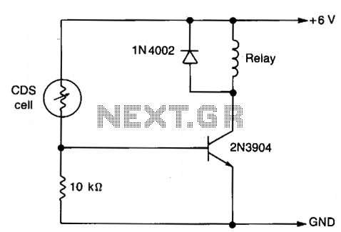
The resistance of the CDS cell decreases when exposed to light, activating the 2N3904 relay driver. The circuit utilizes a Cadmium Sulfide (CDS) photoresistor, which is a light-dependent resistor that changes its resistance based on the intensity of light...
This sound-activated switch allows for control through sound, which can be beneficial not only in robotics but also in home automation applications. The sound-activated switch operates by detecting specific sound frequencies or patterns, typically using a microphone or a sound...
Hall-effect switches offer multiple benefits compared to mechanical and optically coupled switches. They are unaffected by ambient light and dirt, do not jam, and do not experience mechanical wear. The primary disadvantage is that each device typically requires three...
This circuit switches a printer's USB connection between a PC and a laptop. The goal was to create a method for allowing the laptop to use the printer occasionally while maintaining the printer's connection to the PC at all...
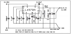
A small-sized and easy-to-build 5V 10A power supply circuit is being sought. This circuit utilizes the L4970A integrated circuit as a 10A switching regulator. It is essential that the power supply input can handle a current of 10A to...
Two inputs, A and B, control the bridge. With both high (or open circuit) both ends of the motor are connected to 0v. Connect A low and Tr2 turns on causing the motor to go forward. Connect B low...