
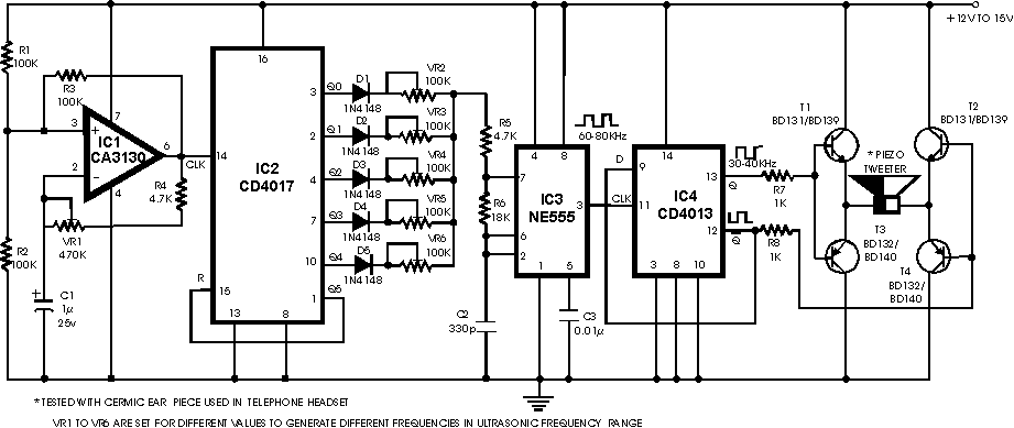
External audio spectrum display circuit diagram

The external audio spectrum display circuit operates by analyzing the audio signals produced by the speakers and translating these signals into visual representations. The circuit typically includes a microphone or a direct audio input to capture the sound waves, which are then processed by the integrated operational amplifiers. These amplifiers boost the audio signal to a usable level for further analysis.
The core of the display system consists of an analog-to-digital converter (ADC), which digitizes the audio signal for frequency analysis. The digital signal processor (DSP) then divides the audio spectrum into predefined frequency bands, corresponding to the five specified frequencies. The DSP determines the amplitude of the audio signal within each band, allowing the circuit to produce a dynamic visual output.
LEDs are employed to represent the amplitude levels visually. Each LED corresponds to one of the frequency bands, lighting up in proportion to the level of the signal within that band. This visual feedback creates an engaging display that reflects the audio being played in real-time.
The design of the circuit allows for easy integration into various audio setups without the need for complex wiring or modifications to existing equipment. The aesthetic appeal of the LED display enhances the overall experience of high-end audio systems, making it a popular choice for audiophiles and enthusiasts looking to elevate both the sound and visual aspects of their audio environments.
Overall, the external audio spectrum display circuit exemplifies a harmonious blend of functionality and design, providing a valuable tool for audio analysis while simultaneously enhancing the visual appeal of audio systems. As shown in the external audio spectrum display circuit, high-end audio equipment are generally audio spectrum display apparatus can keep abreast of both instantaneous playback signal spectrum, but also has elegant and beautiful visual effects. The external audio spectrum display described here, and you do not have to make any sound equipment electrical connections, simply placed in front speakers, you can dynamically display a visual spectrum of the audio signal being played, your sound system both nice and good-looking, considerably. The display is designed in all application specific integrated circuits and integrated operational amplifier circuit is simple, stable, easy to manufacture, easy to use, you can also in 100Hz, 300Hz, 1kHz, 3kHz, the 10kHz5 frequency points (with a certain bandwidth), using five dynamic beam shows the instantaneous level of each frequency point.
External audio spectrum display function, the speaker is playing sound into light-emitting diode light beam dynamic display.
Related Circuits
This is a simplified schematic for the Solar Lifeforce. The design eliminates the expression/CV output features and the toggle for the buffer, making it a straightforward circuit. It may benefit from adding small capacitors between R5 and ground, as...
The astable multivibrator circuit lacks a stable state. In the absence of an external signal, the internal transistors alternately switch between cutoff and saturation at a frequency determined by the RC time constants of the coupling circuits. Therefore, an...
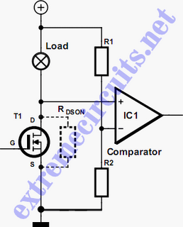
In applications where a MOSFET is used to switch a load, it is relatively straightforward to incorporate short-circuit or overload protection. This can be achieved by utilizing the internal resistance RDS(ON), which generates a voltage drop proportional to the...
This circuit describes a simple 6-bit random number pseudo-generator used to study binary counters and, in particular, shift registers. Some basic background information about binary counters and shift registers is provided. In reality, there are dozens of different shift...
The Colpitts oscillator's frequency is determined by the capacitance of the variable capacitor diode. The center frequency can be adjusted by changing the biasing voltage of the variable capacitor through a 47K potentiometer. A 75 cm telescopic antenna or...
The intended result is for the relay to oscillate and the LEDs to flash when the button is pressed. However, when the button is pressed, the leftmost LED lights constantly, and nothing else happens. There is voltage across the...