
1998 tracker: 1.6 multifuel port injection replaced plugs cap rotor
1. Have an assistant turn the ignition ON and listen near the fuel filler tube for the fuel pump operation, which should last for approximately 3 seconds.
2. Feel for fuel pressure at the fuel return line near the throttle body during the same ignition ON test.
3. Use a Digital Volt-Ohmmeter (DVOM) to measure the resistance between relay terminals A and B, which should indicate infinite resistance, and between terminals C and D, which should be between 63-77 ohms at 77 °F (25 °C). If these values are not met, the relay should be replaced.
4. Connect a 12-volt DC battery to terminals C and D of the relay and check for continuity between terminals A and B.
5. Ensure the battery voltage is at least 11 volts before proceeding with the fuel pressure tests.
6. Install a fuel pressure gauge on the fuel delivery pipe and check the pressure after turning the ignition ON multiple times. For 1.6L engines, the pressure should be 4.6-42.7 psi (250-10 kPa) and for 1.8L engines, it should be 7.4-44.0 psi (270-20 kPa), remaining above 28.4 psi (200 kPa) for one minute after the pump stops.
If fuel pressure is within the specified range, the next steps can be pursued. If no pressure is detected, further testing will be necessary.
To achieve a thorough diagnosis of the fuel system and ensure proper operation of the 1998 Tracker, a systematic approach is required. The initial step involves verifying the fuel pump's functionality by listening for its operation at the fuel filler tube during the ignition ON state. This confirmation is critical as it indicates whether the pump is engaging and functioning for the necessary duration.
Next, assessing the fuel return line for pressure is essential. This will provide insight into the fuel delivery system's integrity and whether the engine is receiving adequate fuel flow. A lack of pressure at this point may suggest issues upstream, such as a malfunctioning fuel pump or a blockage in the fuel lines.
The relay's health is also a significant factor in fuel pump operation. By measuring the resistance across the relay terminals, one can ascertain whether the relay is functioning correctly. If the resistance values deviate from the specified range, replacing the relay is warranted to restore proper electrical connectivity.
Battery voltage plays a crucial role in the fuel system's performance. A voltage lower than 11 volts can lead to inadequate fuel pressure, even if the pump and lines are in good condition. Therefore, ensuring the battery is sufficiently charged is a prerequisite for accurate pressure testing.
Finally, the installation of a fuel pressure gauge allows for precise measurement of the fuel pressure during operation. Following the ignition ON sequence, the pressure readings must be within the specified ranges for the respective engine sizes. If the fuel pressure remains above the critical threshold after the pump ceases operation, the system can be deemed functional. However, if issues persist, further diagnostics will be necessary to identify the root cause, whether it be a failing fuel pressure regulator, a weak fuel pump, or other contributing factors affecting the vehicle's performance.A 1998 tracker it has 1. 6 multifuel port injection system. The vehical is hard to start. when we drive it their is a lack of power it wants to bog down. we have replaced plugs, cap, rotor check catlic ok. disconected the tps still runs the same. could this be the problem I want to make shure Because the part is 300 $ b4 I replace it And is it a simple r&r this sounds as if you have low fuel presure. you need to check the fuel presure, these must have 44psi. the fuel presure regulator may be bad or the fuel pump may be weak please ACCEPT my answer so I can get credit for my work. i don`t receive commission unless you do. i`m not always going to be giving you good news, so please dont let this stand in the way of you accepting my answer.
it does not cost you more money. we will still be able to communicate. Bonuses and positive feedback are appreciated!if you are not satisfied with my answer, please do not leave bad feed back, i will gladly opt out and let another expert handle the question. PLEASE ASK IF YOU NEED MORE HELP Have an assistant turn the ignition ON, while you listen at the fuel filler tube opening.
The operation of the fuel pump should be heard from the fuel filler tube opening for approximately 3 seconds, then it should stop. Fig. Fig. 2: Sounds from the electric fuel pump should be heard from the fuel tank filler tube opening for approximately 3 seconds after the ignition switch is turnedON Once again have your assistant turn the ignition ON, while you feel for fuel pressure at the fuel return line near the throttle body.
Fuel pressure should be felt at the return line for approximately 3 seconds after the ignition switch is turned ON. Using a Digital Volt-Ohmmeter (DVOM) set on the ohmmeter function, measure the resistance between relay terminals A and B, and between terminals C and D.
The resistance between terminals A and B should register infinite resistance (no continuity). The resistance between terminals C and D should be 63-77 ohms at 77 °F (25 °C). If the resistances were not as indicated, replace the relay. Connect a the negative lead of a 12 volt DC battery to terminal D of the relay, and the positive lead to terminal C of the relay. With the relay energized, measure terminals A and B for continuity. There should now be continuity between terminals A and B. If there is no continuity, replace the relay with a new one. Fig. Fig. 7: Attach a 12 volt DC battery to terminals C and D, then measure the resistance between terminals A and B again-replace the relay if the resistance is not as specified Prior to performing the following inspection, ensure that the battery voltage is 11 volts or higher.
If the battery voltage is too low, the fuel pump pressure will be lower than the specified range, even if the fuel pump and fuel lines are in good condition. Fig. Fig. 8: Install a fuel pressure gauge (A) onto the end of the fuel delivery pipe (supply manifold) using a fitting (C) and flexible hose (B) designed specifically for this purpose Turn the ignition switch ON for 3 seconds (without starting the engine), then turn it OFF.
Repeat this three or four times, then check the fuel pressure registered on the fuel pressure gauge attached to the fuel delivery manifold. The fuel pressure should be 4. 6-42. 7 psi (250-10 kPa) for 1. 6L engines, or 7. 4-44. 0 psi (270-20 kPa) for 1. 8L engines, and should remain above 28. 4 psi (200 kPa) for one minute after the fuel pump stops. If the fuel pressure is within the specified range, skip to the next step. If there was no fuel pressure, jump to Sub-Test 1. If the fuel pressure was initially within the specified range but dropped below 28. 4 psi (200 kPa) within one minute after the fuel pump stopped, skip to Sub-Test 2. If the fuel pressure was too low, skip to Sub-Test 3. If the fuel pressure was too high, skip to Sub-Test 4. Allow the engine to idle and observe the fuel pressure on the gauge. The fuel 🔗 External reference
Related Circuits
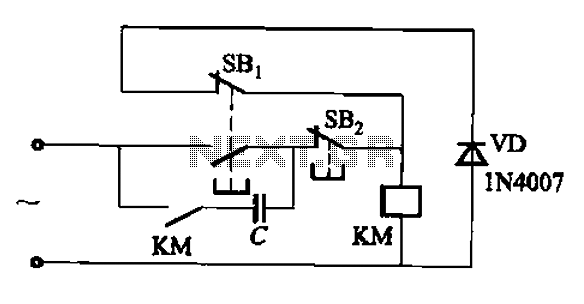
An AC contactor switch, when used with DC or pulse DC excitation, can minimize short circuit and core power consumption. This results in a significant reduction in the power consumption of the electromagnet, which can eliminate noise and reduce...
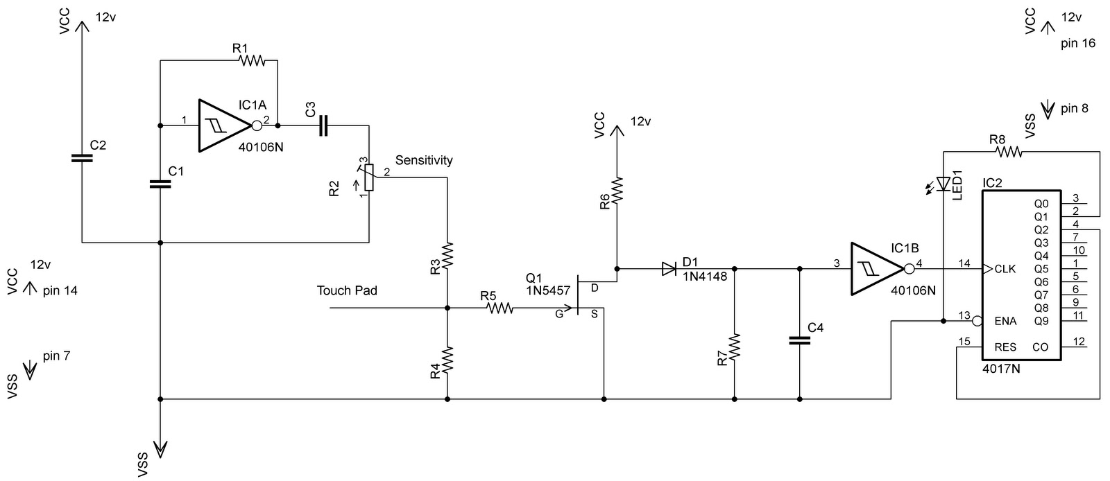
In the previous post regarding a capacitive touch switch, the output was activated only while the touch was maintained. This means that the circuit would drive the load only during the touch, and once the touch was removed, it...
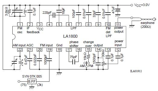
This portable AM/FM radio circuit is designed using the LA1800 integrated circuit (IC) along with several external components. The LA1800, manufactured by Sanyo Semiconductors, requires only a few additional components for its operation. The output signal is directed to...

Some games are easier to play with digital joystick instead of analogue type. Unfortunately PC has only analogue joystick connector, which makes it impossible to connect normal digital joystick to it. But with a little adapter circuit, it is...
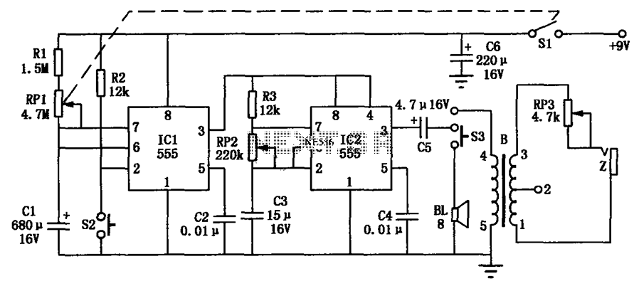
The hypnosis massage device is a compact electronic timing circuit that utilizes two 555 timers to address the health needs of individuals seeking relaxation. The circuit comprises three main components: a timer circuit, a hypnosis circuit, and a massage...
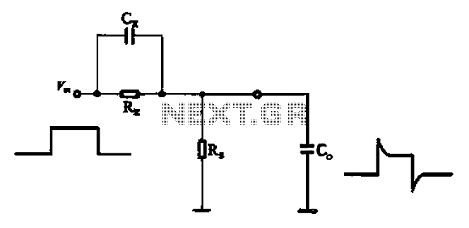
Accelerate the role of capacitance to reduce the delay of the waveform. In parallel with the signal input resistor RK, a speed-up capacitor CK is used to sharpen the pulse edge, thereby reducing the impact of small input capacitance. In...