
Low Cost Capacitive Touch Switch II circuit schematic with explanation
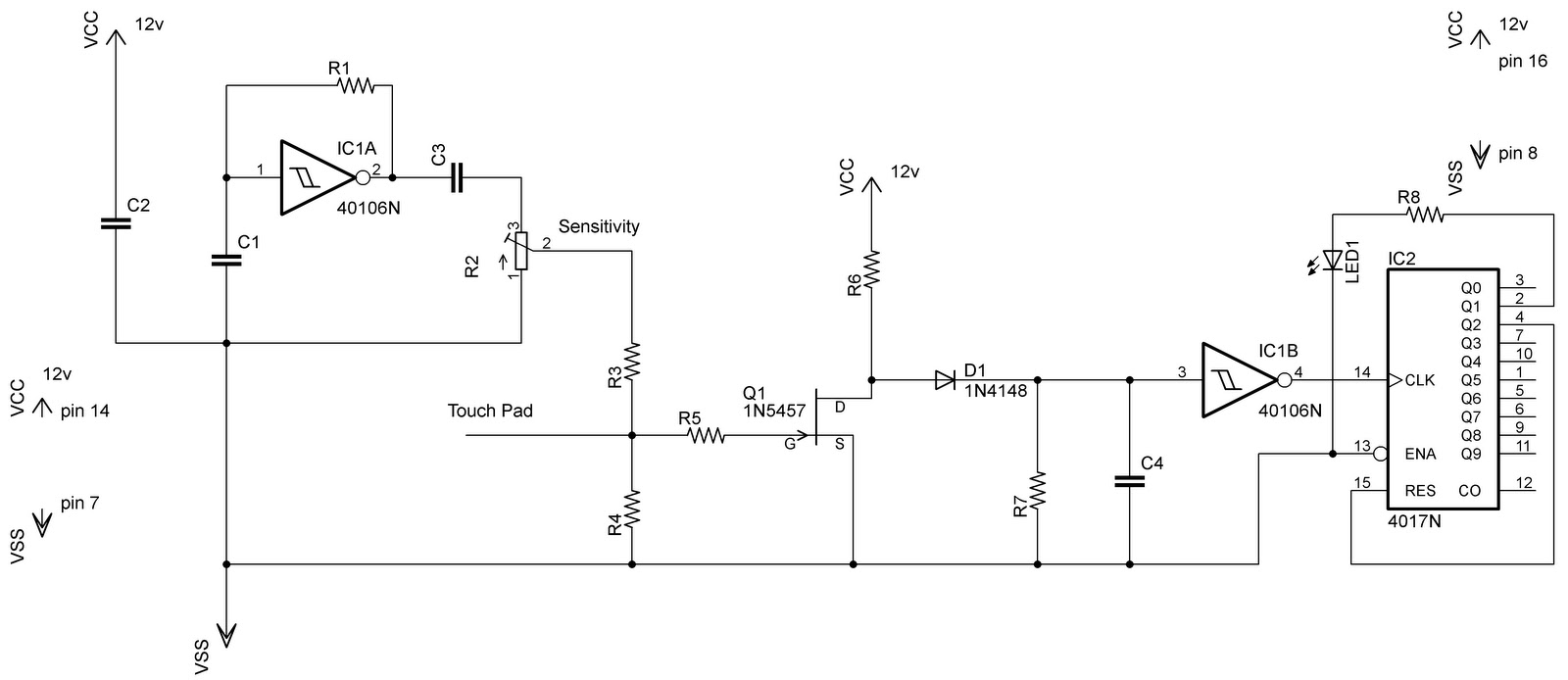
The touch switch circuit designed with the CD4017 decade counter provides a versatile solution for applications requiring a touch-activated on/off mechanism. The CD4017 is a popular decade counter IC that counts from 0 to 10 and provides ten outputs (Q0 to Q9). In this configuration, the touch plate serves as the input trigger, sending a pulse to the clock input of the CD4017 every time it is touched.
When the circuit is powered, the CD4017 begins at an initial state of Q0 being high and all other outputs low. The output connected to Q1 is used to drive the load. Upon the first touch of the plate, the CD4017 increments to Q1, turning on the load. A second touch increments the counter again, resetting the output to Q0, which turns off the load. This toggle function effectively allows the user to control the load with a single touch plate, simplifying the user interface.
Additional components may be incorporated into the circuit for enhanced functionality, such as debounce circuitry to prevent false triggering due to noise or unintended touches. A capacitor can be placed in parallel with the touch plate to filter out high-frequency noise, ensuring that only deliberate touches are registered.
Furthermore, the use of a pull-down resistor at the input can help stabilize the input signal when the touch plate is not activated, preventing floating states that might lead to erratic behavior. The circuit can be powered by a standard DC voltage supply, compatible with the operating range of the CD4017, typically between 3V and 15V.
This design not only meets the requirement for a touch-activated switch but also offers a reliable and efficient method for controlling electrical loads in various applications, including lighting systems, appliances, and automated devices.In my previous post of capacitive touch switch, it gives the o/p as long as you touch it. Means it was only drive the load when you touch it, and when you remove your hand/finger then it was not able to drive the load. Tough that touch switch circuit can be used in various apps but does not meet my requirements. So by changing the circuit a little bit i am able to design a touch switch that behave like a normal switch i. e touch to on and touch to off. For this i used CD4017 decade counter. Output of 40106 drives this counter and load is connected to the pin2 of the counter, and reset is to pin4. When you touch the touch plate (wire in my case) a pulse is provided to the counter and it increments its o/p.
So as the load is connected to the Q1 of counter, the o/p is high to drive the load. Similarly if you want to switch off the load and again touch the plate; counter will increment again and reset itself and make Q0 high. As your load is not connected to this pin it will go off. That is all!. 🔗 External reference
Related Circuits
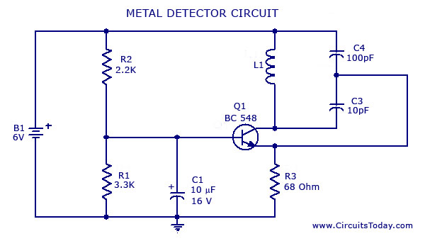
A simple metal detector circuit diagram and schematic using a single transistor and a radio. This metal detector/sensor project is easy to make and is an application of a Colpitts oscillator. The metal detector circuit utilizes a single transistor in...
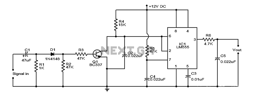
This document provides an overview of a simple circuit diagram for frequency (F and V) voltage conversion. It describes a digital frequency meter circuit primarily based on the LM555 timer IC, which is commonly used in various applications, including...
This tremolo effect circuit utilizes the XR2206 and the TCA730 integrated circuits, which are designed as an electronic balance and volume regulator with frequency correction. The tremolo effect circuit operates by modulating the amplitude of an audio signal, creating a...
The power used for realignment is considered a loss in the context of the overall circuit. Due to the hysteresis loss in the saturable-core reactor, the power gain is relatively low. Adding a rectifier to the load circuit can...
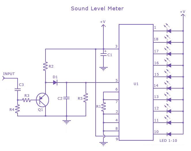
This is a single-chip sound level meter that can be used to display the sound level of an amplifier or simply the sound level from a microphone. The core component of the circuit is the IC LM3915 Audio Level...
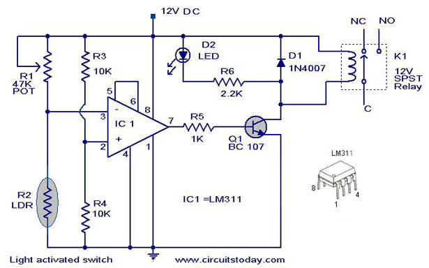
A simple light-activated switch circuit with a diagram and schematic using IC LM311 wired as a voltage comparator and an LDR that acts as a light sensor. The described circuit utilizes the LM311 integrated circuit, which functions as a voltage...