
Convert Atari-style joystick to PC joystick port

The circuit described serves as an adapter for connecting a digital joystick, such as those commonly used with Atari systems, to the analogue joystick port of an IBM PC. The functionality of this circuit relies on the conversion of digital signals from the joystick into analogue signals that the PC can interpret.
The primary components of the circuit include a microcontroller or a logic IC, resistors, capacitors, and possibly an operational amplifier to facilitate the conversion process. The digital joystick typically outputs signals in a binary format, indicating the position of the joystick in the X and Y axes. The adapter circuit captures these signals and translates them into varying voltage levels that correspond to the analogue inputs of the PC.
The circuit diagram should include the joystick connectors, where the digital joystick is connected to the input side of the circuit. The output side connects to the PC's joystick port. The microcontroller or logic IC will read the digital signals and use a method such as pulse-width modulation (PWM) or a digital-to-analogue converter (DAC) to create the necessary analogue signals.
Resistors may be used to form voltage dividers that scale the output signals appropriately, while capacitors might be employed for signal smoothing to ensure that the analogue signals are stable and free from noise.
In terms of power supply, the circuit can be powered via the joystick port or through an external source, depending on the design. The circuit is compact and can be housed in a small enclosure to facilitate easy connection and portability.
This adapter circuit allows users to enjoy games that were originally designed for analogue joysticks, providing a flexible solution for gaming enthusiasts who prefer digital joysticks. The design can be further optimized for responsiveness and accuracy, ensuring a seamless gaming experience.Some games are easier to play with digital joystick instead of analogue type. Unfortunately PC has only analogue joystick connector, which makes it impossible to connect normal digital joystick to it. But with a little adapter circuit, it is possible to use Atari style digital joystick with IBM PC joystick interface.
The circuit adapts the joystick connectors and converts digital joystick movement signals to analogue signals. The circuit can be used with any PC game to replace the original analogue joystick. 🔗 External reference
Related Circuits
This is a 28VDC to 5VDC switching converter circuit. As a switch-mode voltage regulator, this circuit provides higher efficiency than linear regulator types. The 28VDC to 5VDC switching converter circuit operates by converting a higher voltage direct current (DC) input...
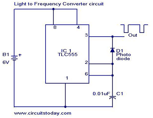
A simple light-to-frequency converter circuit with a diagram and schematic. It is used as a light intensity measurement circuit. The design utilizes the TLC555, a CMOS version of the NE555 timer IC. The light-to-frequency converter circuit is designed to convert...

The pressure transmitter circuit data acquisition system utilizes the 1B31, an 18-bit A/D converter (AD1170), and an MCS-51 microcontroller. The configuration, as depicted in the accompanying diagram, features a full-scale output voltage of 10 mV from the pressure transmitter...
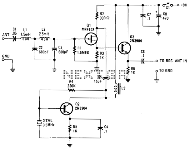
The VLF Converter is designed to receive signals for general coverage in shortwave receivers. It can pick up various unusual signals on frequencies below 15 kHz. This converter effectively transforms frequencies ranging from 0 to 250 kHz into a...
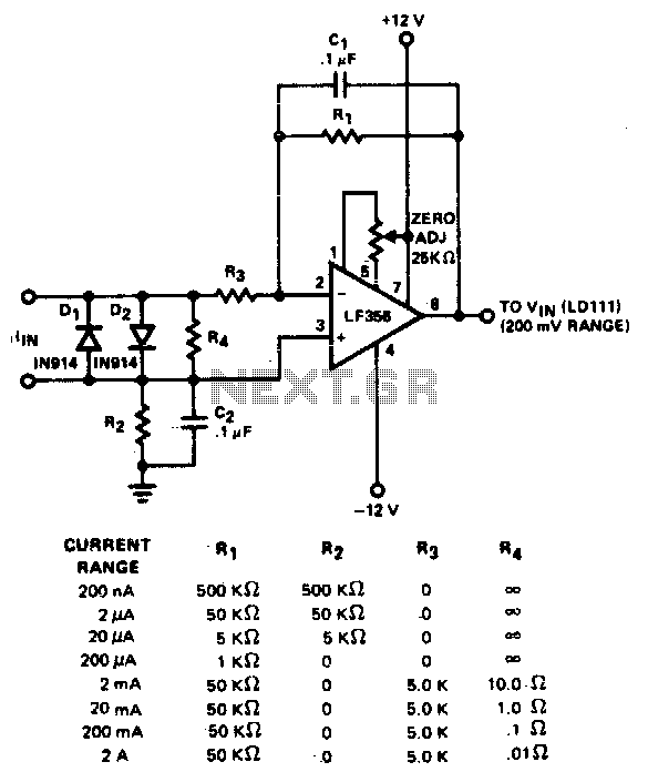
The converter features eight decades of current range. The circuit is intended to be used with the 200 mV range of a DVM. The described converter circuit is designed to accommodate a wide range of current measurements, spanning eight decades....
This project originated from an interest in a new form of radio transmission known as Digital Radio Mondiale (DRM), which is a digital shortwave transmission method. While there are a few devices available from Europe for decoding these digital...