
1999 mercury sable: wiring diagram illumination a 3.0L vin U. I
The circuit for the clock and radio screen illumination in a 1999 Mercury Sable GS is critical for ensuring that the driver can easily read the time and radio settings, especially during nighttime driving conditions. The illumination system typically involves a series of interconnected components, including the instrument cluster, the radio unit, and the associated wiring harnesses.
In this vehicle model, the illumination for the clock and radio display is generally controlled by the vehicle's lighting circuit. When the vehicle's headlights are turned on, a voltage is supplied to the illumination circuit, which activates the backlighting for both the clock and radio display. This is often achieved through a dimmer switch that allows the driver to adjust the brightness according to their preference.
The wiring diagram will illustrate the connections between the headlight switch, the dimmer switch, and the instrument cluster. The circuit typically includes a fuse that protects against overloads, ensuring that the system operates safely. Each component in the circuit should be checked for continuity and proper connection to ensure that the illumination functions correctly.
To troubleshoot any issues with the clock and radio screen illumination, it is advisable to inspect the wiring harness for any signs of damage or corrosion, test the voltage at the dimmer switch, and verify that the bulbs within the clock and radio units are functioning. Proper diagnosis may require the use of a multimeter to measure voltage and continuity throughout the circuit.The wiring diagram for the clock and radio screen illumination for a 1999 mercury sable with a 3. 0L vin U. I have searched for hours on alldata and MichellOnDemand and have found absolutely nothing. Please help! I don`t know if it matters, but the vehicle is a mercury sable GS, not LS. I appologize for not specifying that earlier. Which one of these circuits in your diagrams would run the screen that has the clock on it Ask-a-doc Web sites: If you`ve got a quick question, you can try to get an answer from sites that say they have various specialists on hand to give quick answers. Justanswer. com. Traffic on JustAnswer rose 14 percent. and had nearly 400, 000 page views in 30 days. inquiries related to stress, high blood pressure, drinking and heart pain jumped 33 percent. Because of your expertise, you armed me with enough ammunition to win the battle with the dealer. They are installing a fuel filter and fuel pump at no charge to me. Molly USA I needed help with my car on Saturday morning. got a response in 5 minutes, and it was the perfect solution. Thanks again to your service. Jason V. Kirkland, WA I would (and have) recommend your site to others I was quite satisfied with the quality of the information received, the professional with whom I interacted, and the quick response time.
Thanks, and be sure that I`ll be back whenever I need a question answered in a hurry. Stephanie P Elm City, NC used your service this weekend with "Trecers" help. thank you, thank you, thank you. replaced an A/C fan motor. Local Auto Zone had part. $15. 00 "tracer" fee and $40. 00 for parts, I saved several hundreds of dollers at a shop. i will recommend you and use you in the future. David L. Richmond, TX 🔗 External reference
Related Circuits
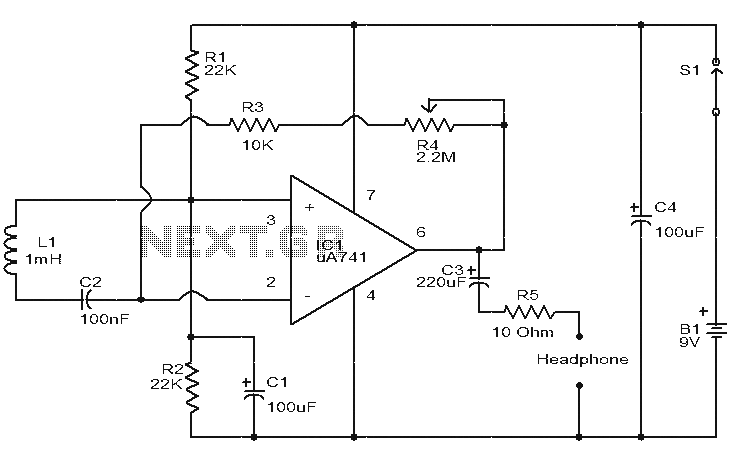
This is a simple circuit designed to detect electromagnetic radiation, including hidden wiring. It utilizes a 1mH inductor to sense the electric field. The induced voltage from the inductor is amplified by an operational amplifier (op-amp). An audio headset...
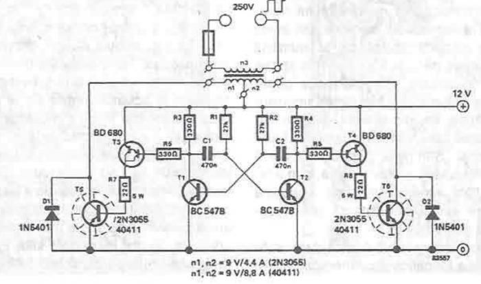
A simple portable converter that transforms 12V to 250V can be constructed using this circuit diagram. This converter is intended for portable use with a 12V car battery. A built astable multivibrator, consisting of transistors T1 and T2, generates...
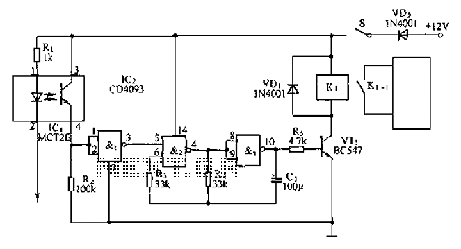
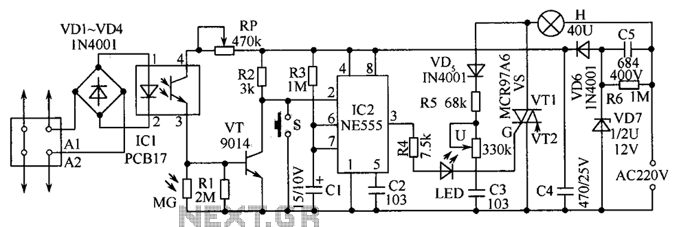
An anti-theft car audio system circuit is depicted, powered by a 12V DC supply from the car battery. Upon closing switch S1, the light-emitting diode in optocoupler IC1 activates, causing the phototransistor to conduct. This results in a high-level...
The electric car remote control circuit diagram enables the model car to move forward and backward, as well as turn left and right. It is simple and easy to operate. The radio remote control receiver demodulation circuit utilizes TWH9238...
The telephone table lamp is designed to automatically illuminate during night ringing or when the phone is off-hook. After hanging up, the lamp will extinguish after a delay of 45 seconds. It is typically used as a general-purpose lamp...
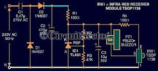
An infrared remote control tester circuit that can be constructed inexpensively. This IR tester is built around an infrared receiver module TSOP1738. The remote control's state can be observed through the sound of a buzzer. The circuit is highly...
Warning: include(partials/cookie-banner.php): Failed to open stream: Permission denied in /var/www/html/nextgr/view-circuit.php on line 713
Warning: include(): Failed opening 'partials/cookie-banner.php' for inclusion (include_path='.:/usr/share/php') in /var/www/html/nextgr/view-circuit.php on line 713