
1KHz IR transmitter circuit
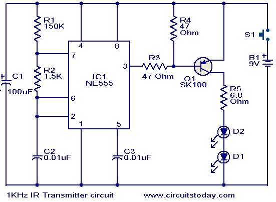
The described circuit operates effectively as a low-power infrared transmitter, leveraging the NE555 timer's versatility to generate a stable 1 kHz pulse train. The astable multivibrator configuration allows for continuous oscillation, producing square waves that can be efficiently amplified. The choice of the SK100 transistor for amplification is appropriate due to its capability to handle the current required to drive the IR LEDs, ensuring that the emitted IR light is sufficient for remote control applications.
The resistors R1 and R2, along with capacitor C2, are critical in determining the frequency of oscillation. The values of these components can be calculated using the standard formula for the frequency of an astable multivibrator:
\[ f = \frac{1.44}{(R1 + 2R2) \cdot C2} \]
Where \( f \) is the frequency in hertz, \( R1 \) and \( R2 \) are in ohms, and \( C2 \) is in farads. Adjusting these components allows for fine-tuning of the output frequency to meet specific application requirements.
The circuit's operation is initiated by the push-button switch S1. When pressed, S1 completes the circuit, allowing current to flow and activating the NE555 timer. This results in the generation of IR pulses that can be used for various remote control functions, such as operating electronic devices or controlling systems from a distance.
Overall, the design is straightforward and can be implemented with commonly available electronic components, making it accessible for hobbyists and professionals alike. The effective range of approximately 10 meters makes it suitable for many practical applications, while the simplicity of the circuit allows for easy troubleshooting and modifications.This circuit was designed in response to a request from my reader. What he asked for was a 1KHz IR transmitter circuit for some remote control application. I think this circuit may satisfy him. Any way this circuit can be used where ever a low power IR transmitter of 1 KHz operating frequency is needed. This transmitter can transmit up to a distan ce of about 10 meters. The circuit is based on a NE555 timer IC (IC1) which is wires as an astable multivibrator to produce 1KHz pulses. The output pulses of the IC1 will be amplified by the Q1(SK100) to drive the two IR transmitter LEDs wired serially.
The resistors R1, R2 and capacitor C2 determines the operating frequency of the IC. The circuit starts emitting IR pulses when ever the push button switch S1 is pressed. 🔗 External reference
Related Circuits
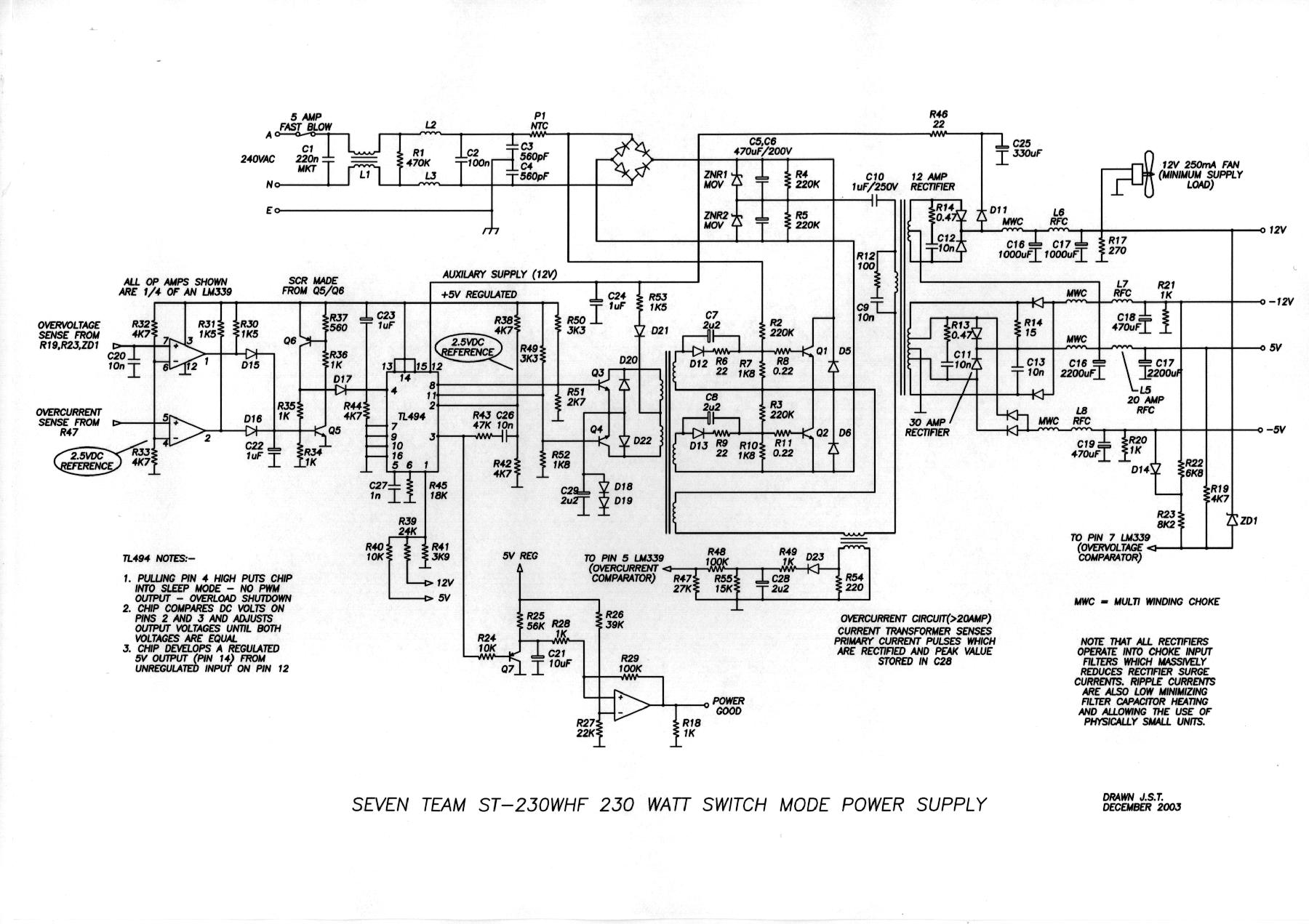
An even power device is designed to supply energy to a computer. It is typically intended for converting alternating current (AC) into low-voltage direct current (DC). Without this component, a computer is merely a collection of metal and plastic...
The apparatus consists of a cavers point detection circuit and a triggering display circuit. The cavers instrument functions as a test probe, which, when held in one hand, can detect acupuncture points by touching the skin with another probe....
This transmitter emits an FM signal within the 88 to 108 MHz frequency range, featuring a tone of 19 kHz. This tone can activate the FM MPX pilot carrier indicator, allowing interfacing with external devices. L4 is designed for...
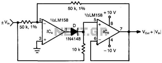
When the input voltage is positive, the output of ICA is negative, resulting in diode D not conducting; therefore, the output of ICB is positive. Conversely, when the input is negative, the output of ICA becomes positive. Diode D...
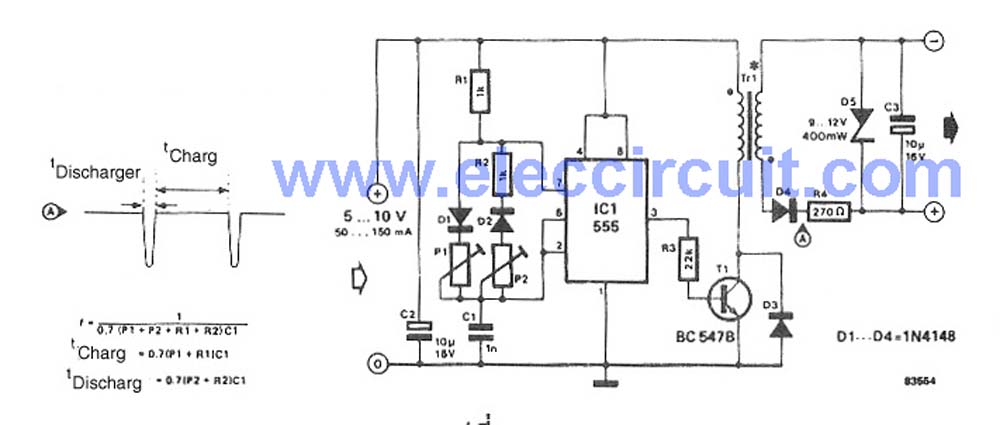
This circuit is a simple DC to DC converter designed for digital circuits. It operates with a supply voltage of 5V and provides an output voltage that steps up to a maximum of 10V-12V DC. The circuit utilizes an...
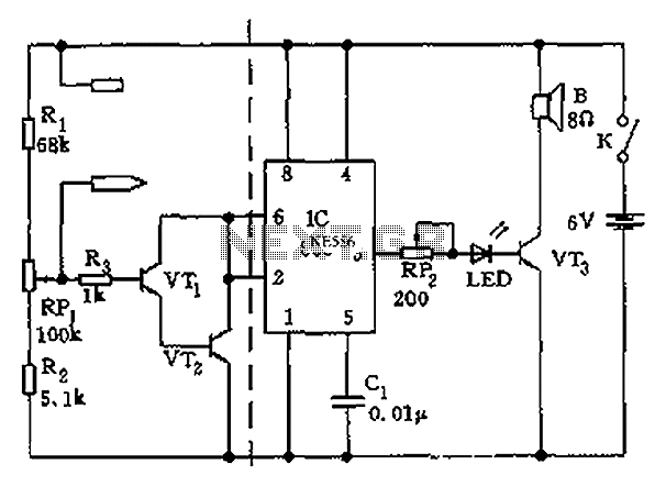
In this intercom schematic, an 8-ohm speaker is used as both a microphone and a listening speaker. A 10K potentiometer controls the volume, and the total gain can be adjusted. This intercom circuit utilizes an 8-ohm speaker in a dual...
Warning: include(partials/cookie-banner.php): Failed to open stream: Permission denied in /var/www/html/nextgr/view-circuit.php on line 713
Warning: include(): Failed opening 'partials/cookie-banner.php' for inclusion (include_path='.:/usr/share/php') in /var/www/html/nextgr/view-circuit.php on line 713