
Simple DC Converter For Digital Circuit by IC 555
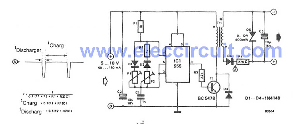
The circuit operates by employing the 555 timer in an astable mode configuration, which generates a pulse-width modulation (PWM) signal. This PWM signal is then used to control a switching element, typically a transistor or a MOSFET, that regulates the energy transferred to an inductor. The inductor stores energy when the switching element is turned on and releases it to the output when the switching element is off, effectively increasing the voltage.
The key components of this circuit include the 555 timer IC, resistors, capacitors, an inductor, and a diode. The values of the resistors and capacitors connected to the 555 timer determine the frequency and duty cycle of the PWM signal. Selecting appropriate values for these components is crucial for achieving the desired output voltage.
The inductor is chosen based on the required output current and voltage ripple specifications. A Schottky diode is often used for its fast recovery time, which minimizes losses during the energy transfer phase. The output capacitor smooths the voltage, reducing ripple and providing a stable output voltage.
This simple DC to DC converter is suitable for powering low-power digital circuits that require a higher voltage than the available supply voltage. It is essential to ensure that all components are rated for the voltages and currents they will encounter during operation to prevent damage and ensure reliability. Proper layout and grounding techniques should also be employed to minimize electromagnetic interference (EMI) and ensure stable operation.This circuit Simple DC to DC Converter For Digital Circuit. It use Volt supply 5V Only, To Output Step up Volt 10V-12V DC max. I use IC 555 ( hot ic Timer) for.. 🔗 External reference
Related Circuits
Half of a Motorola MG14538B dual precision retriggerable monostable multivibrator is utilized to create an extended on-time timer circuit. This type of circuit can function as a switch debouncer. Such circuits are commonly implemented in digital applications, where every...
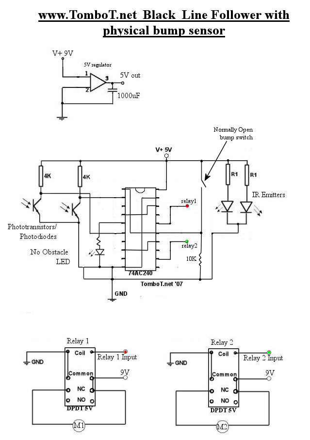
The motors will be powered by the full source voltage, so it is important to ensure that this does not cause the robot to operate too quickly. The Firebot utilizes GM3 motors powered by a 9V battery; however, in...

To invoke the Spectrum +3 diagnostic routines, first reset the machine while holding the BREAK key down. This will bring up the test card display. Next, hold down the QAZMLP keys for a few seconds until the diagnostic title...
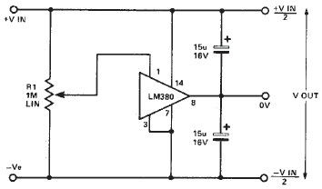
A simple split power supply circuit can be designed using the schematic diagram based on the LM380 audio power integrated circuit (IC). The output voltage regulation is dependent on the circuit feeding the LM380. The power dissipation is approximately...

The NE571 and LM1894N form a dynamic expander circuit that enhances performance. This dynamic expander utilizes a variable bandpass filter with the LM1894N. It is particularly effective for dynamic expansion, requiring an RMS rectifier to mitigate noise modulation effects,...
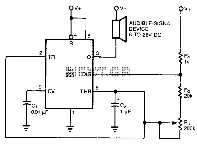
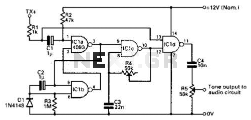
The simple circuit converts the continuous beep of an audible-signal device, such as a Mallory sonalert, into a unique warble or chirp. The values of resistor R and capacitor C2 determine the specific tone quality produced. With a 1kΩ...