
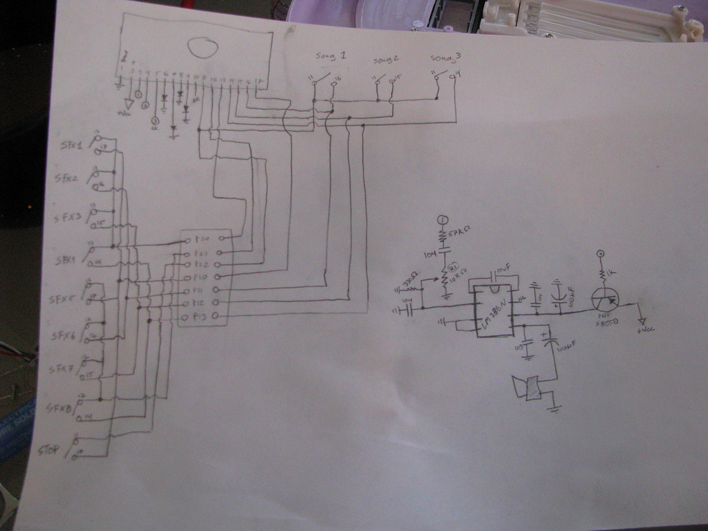
A small DC motor control circuit a
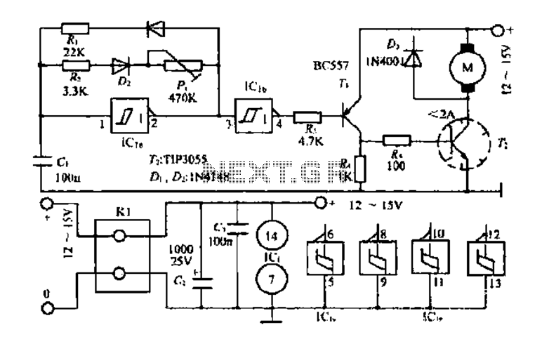
The core multi-resonant circuit 40 L06 is designed to operate efficiently under varying load conditions. The circuit functions by utilizing a combination of capacitors and inductors to create multiple resonant frequencies, allowing it to adapt to different operational parameters. The auxiliary electric signal serves as a control mechanism, ensuring that the circuit remains stable even when the input signal drops below a predetermined threshold.
Key components include CI, which acts as a capacitor for energy storage, D1, a diode for rectification, and Ri, a resistor that influences the charging rate. The fast charging capability of the circuit is essential for applications requiring rapid energy delivery, such as in motor drives or pulse modulation systems.
The monitoring of the voltage across the 1.5msiN member is critical for maintaining circuit integrity. If this voltage exceeds a specified high limit, the output is automatically reduced, preventing potential damage to downstream components. This feedback loop is vital for ensuring safe operation within the defined parameters.
The discharge characteristics of the prototype circuit indicate a quick response time, with a discharge duration of 0.2 milliseconds for rapid applications and a longer duration of 25 milliseconds for slower, more controlled operations. This flexibility allows the circuit to function effectively across a range of duty cycles, from 5% to 90%, making it suitable for various applications in industrial and commercial settings.
The output pulse generated by the circuit is capable of driving motors directly, providing a robust solution for electromechanical systems. The design minimizes resistance in the pathway to ensure maximum efficiency and performance, while the feedback mechanisms allow for precise control over the output characteristics, enhancing the overall reliability of the circuit in practical applications.Core multi-resonant circuit 40 L06 collapse is 1C.. Auxiliary electric f below its low threshold, open Icl. Output (2 feet) for the business l NIE., CI by D1 and Ri fast chargi ng. The voltage across the 1.5msiN member high column lcl. F] high limit, so tho output goes low. 1: Is the CI by the island, code and P discharge. Prophecy prototype circuit discharge time} Shu 0.2 milliseconds and 25 milliseconds. Therefore, the duty cycle of the output signal of between 5% and 90u/u change of. Groom bow and then by Ha shed backward to shake f group, and n H and the transistor in IC, h output pulse (4 feet) is still weeks rltiIA] turned on drive motor. Only minimal resistance elbow, turn contingent highest.
Related Circuits
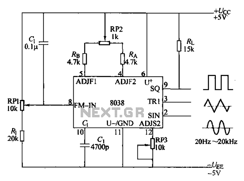
The audio function generator integrated circuit ICL8038 is capable of producing square waves, triangle waves, and sine waves. The electrical resistance and potentiometer RP1 are utilized to determine the 8-pin DC potential Ua, which is typically set to 2Ucr/3....

The PGA202 offset voltage correction circuit is designed to correct both input and output offset voltages. There are four different gain settings for the PGA202, which result in slight variations in input offset voltage. A 50k potentiometer is used...
This light-sensitive automatic light switch circuit is designed to be connected to the main 220V supply. The circuit will activate a 220V lamp during nighttime. The light-sensitive automatic light switch circuit operates by utilizing a light-dependent resistor (LDR) to detect...
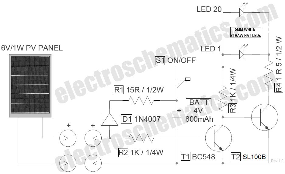
The circuit for the LED solar lantern lights is designed using a 6V/1W solar panel (photovoltaic panel) and a 4V/800mAh lead-acid battery. The schematic for the LED solar lantern circuit incorporates a solar panel that converts sunlight into electrical energy....
A recent thrift shopping experience revealed a toy that appears to be suitable for circuit bending. The toy was found without batteries, preventing any testing at the store. It may be beneficial to bring batteries during future visits or...
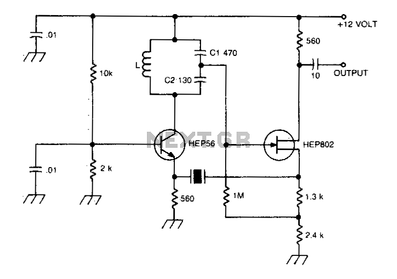
A typical Butler oscillator operating within the frequency range of 20 to 100 MHz incorporates a Field Effect Transistor (FET) in the second stage of its configuration. The circuit exhibits reliability issues when utilizing two bipolar transistors. In some...
Warning: include(partials/cookie-banner.php): Failed to open stream: Permission denied in /var/www/html/nextgr/view-circuit.php on line 713
Warning: include(): Failed opening 'partials/cookie-banner.php' for inclusion (include_path='.:/usr/share/php') in /var/www/html/nextgr/view-circuit.php on line 713