
One circuit alarm phase

The described circuit operates on the principle of monitoring the voltage levels in a 3-phase system to ensure the integrity of the power supply. The circuit includes a voltage sensing mechanism connected to point A, which is strategically placed to monitor the phase voltages. Under normal operating conditions, the voltage at this point remains at or near zero volts, indicating that all three phases are functioning correctly.
In the event of a phase failure, the voltage at point A will rise above the normal threshold. This change is detected by a comparator circuit which is designed to trigger when the voltage exceeds a predefined level. The output of the comparator activates an indicator light (signal H) and a bell (HA alarm), alerting personnel to the fault condition.
The circuit may also include additional components such as resistors and capacitors to filter noise and stabilize the readings, ensuring reliable operation. A reset mechanism could be integrated to allow for the manual silencing of the alarm once the issue has been addressed, preventing unnecessary disruptions.
Overall, this phase failure detection circuit is essential for protecting sensitive electrical equipment, particularly asynchronous motors, from damage due to power supply irregularities. Its design emphasizes responsiveness and reliability, making it a critical component in industrial electrical systems.3-phase power, would endanger the electrical equipment (especially asynchronous motor) security, in order to detect phase failure, it can be made with a broken alarm. Circuit s hown in Figure 13-110. When the power supply is normal, A point voltage about as ov, no alarm; when phase loss (one phase or two-phase), A point voltage increases, the signal H is lit, bells HA alarm.
Related Circuits
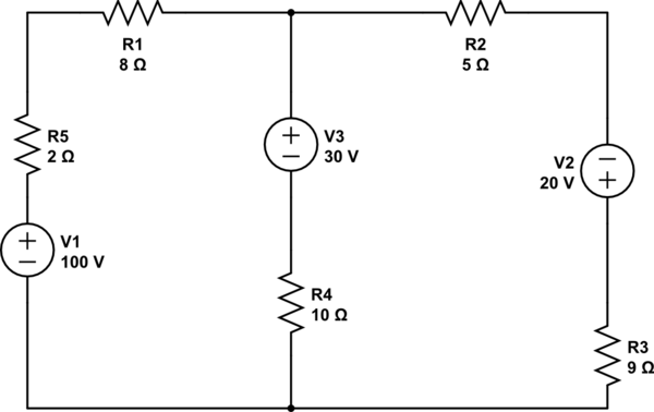
Using the superposition theorem, it is necessary to determine the current at all three nodes of the circuit. The current from the source, denoted as i_1, represents the current through V1 when other voltage sources are shorted out, in...
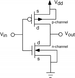
The fundamental issue presented is the perception that logic gates in a circuit seem to generate power from nothing, which contradicts the principles of physics. For instance, consider two NOT gates connected in series. It appears that the first...

A simple audio amplifier can be designed using the LM380 along with a few external components. This amplifier features a wide supply voltage range, an input impedance of 150 kΩ, low distortion, and a current capability of 1.3 A. The...
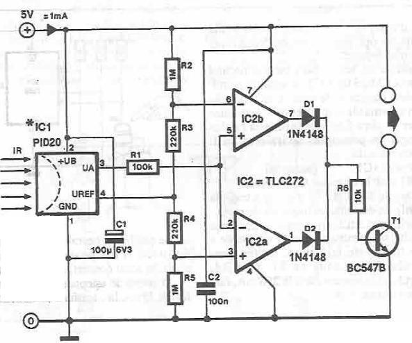
This infrared detector circuit utilizes the PID20 integrated circuit manufactured by Siemens, which converts thermal radiation into electrical impulses. It includes an operational amplifier and several electronic components. The output signal at pin 3 is compared to a reference...
This article discusses the 128K EPROM (27C128), which was used in the 1986 to 1989 IROC-Zs equipped with the 1227165 ECM. The purpose is to provide a foundational understanding of binary and hexadecimal systems. Binary numbers consist solely of...
A thermistor is utilized in the circuit for heat sensing, while two 5K variable resistors are incorporated to calibrate the circuit for activating the relay at the desired temperature. The inclusion of a 1N4007 diode across the relay serves...