
1khz sinewave generator
The inverted Wien bridge oscillator is a type of electronic oscillator that produces sine waves with high stability and low distortion. It operates on the principle of positive and negative feedback, utilizing an RC network to determine the frequency of oscillation. The circuit typically consists of operational amplifiers, resistors, and capacitors arranged to create a feedback loop that sustains oscillation.
In the inverted Wien bridge configuration, two resistors and two capacitors form the frequency-determining network. The resistors are connected in series, while the capacitors are in parallel, which allows for precise tuning of the frequency. The output frequency can be calculated using the formula:
\[ f = \frac{1}{2\pi R_1 R_2 C_1 C_2} \]
where \( R_1 \) and \( R_2 \) are the resistances, and \( C_1 \) and \( C_2 \) are the capacitances in the circuit. For a frequency of 1 kHz, appropriate values for the resistors and capacitors must be selected to meet this requirement.
The operational amplifier serves as the active element in the circuit, providing the necessary gain to sustain oscillation. The gain of the op-amp must be carefully set to ensure that it compensates for losses in the circuit while maintaining stability. A common approach to achieve this is by using a variable resistor in the feedback loop, which allows for automatic gain adjustment as the amplitude of the oscillation changes.
In practical applications, the output of the circuit can be connected to various loads, such as audio devices or signal processing equipment. The sine wave generated by the circuit is typically clean and free from harmonics, making it suitable for testing and calibration purposes in electronic systems. Proper power supply decoupling and layout considerations should be taken into account to minimize noise and interference in the output signal.This circuit generates a good 1KHz sinewave using the inverted Wien bridge configuration.. 🔗 External reference
Related Circuits
Sound effects generators trying to imitate rain sound or sea surf are well known to hobbyists from many years: their purpose is to induce relaxation and sleep or to help in concentration and study. The sound generated is restrained...
The objective is to design a square-wave generator with an output range of 0 to +5V. Additionally, the design should allow for the modification of the signal to enable adjustment of the duty cycle of the pulse (PWM). The square-wave...

A tapped-coil Colpitts oscillator is utilized at Q1 to deliver four tuning ranges: 1.7 to 3.131 MHz, 3.0 to 5.6 MHz, 5.0 to 12 MHz, and 11.5 to 31 MHz. A Zener diode (D2) is incorporated at Q1 to...
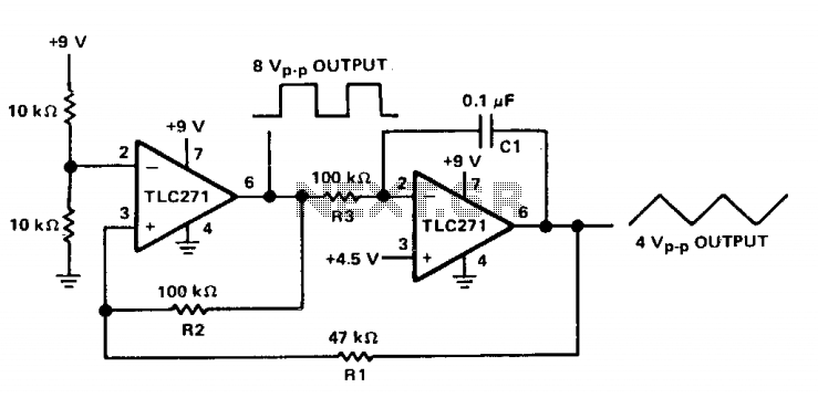
The circuit features both square-wave and triangle-wave outputs. The left section operates similarly to a comparator circuit that employs positive feedback for hysteresis. The inverting input is biased at half the Vcc voltage using resistors R4 and R5. The...
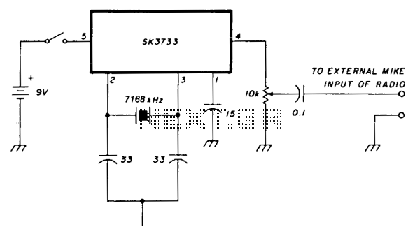
Most European repeaters require activation with a 1750-Hz tone. The SK3733 (also referred to as ECG1197) integrated circuit includes a crystal oscillator and features division factors of 256, 1024, 2048, and 4096. A 7168-kHz crystal is utilized; the divide-by-4096...
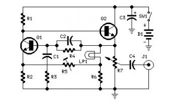
Set R5 to read 1V RMS on an audio millivoltmeter connected to the output with R7 rotated fully clockwise, or to view a sine wave of 2.828V peak-to-peak amplitude on the oscilloscope. An audio amplifier is an electronic device...