
Function generator
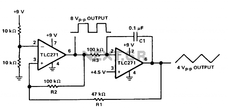
The described circuit is a waveform generator capable of producing square and triangle waves, commonly utilized in various applications such as signal processing, audio synthesis, and control systems. The first stage, which mimics a comparator, utilizes positive feedback to create hysteresis, ensuring stable switching between high and low states. This configuration minimizes noise susceptibility and enhances the reliability of the output signals.
The inverting input's biasing at half the Vcc is crucial for determining the threshold levels at which the circuit toggles between its output states. The feedback mechanism, where the output is routed back to the non-inverting input, is integral for controlling the oscillation frequency. This feedback loop allows for precise frequency modulation, which is essential in applications where timing is critical.
The amplitude of the square wave output, specified as 8 V peak-to-peak, indicates the maximum voltage swing of the first stage, which is vital for ensuring the generated signals are robust enough for downstream applications. The second stage's role as an op-amp integrator allows it to convert the square wave into a triangle wave, providing a linear ramp signal that can be advantageous in various signal processing tasks.
Resistor R3, as the input element, plays a significant role in determining the circuit’s response to input signals, while capacitor C1, serving as the feedback element, influences the integrative properties of the second stage. The relationship between resistors R1 and R2 is critical, as it directly affects the amplitude of the triangle wave in relation to the square-wave output, allowing for flexibility in waveform shaping.
The formula governing the frequency of oscillation for both waveforms is essential for designers and engineers to understand, as it allows for precise control over the generated frequencies, ensuring they meet the requirements of the specific application. Overall, this circuit exemplifies the integration of comparator and integrator functionalities to produce versatile waveform outputs.The circuit has both square-wave and triangle-wave output. The left section is similar in function to a comparator circuit that uses positive feedback for hysteresis. The inverting input is biased at one-half the Vcc voltage by resistors R4 and R5. The output is fed back to the non-inverting input of the first stage to control the frequency. The amplitude of the square wave is the output swing of the first stage, which is 8 V peak-to-peak. The second stage is basically an op amp integrator. The resistor R3 is the input element and capacitor Cl is the feedback element. The ratio R1/R2 sets the amplitude of the triangle wave, as referenced to the square-wave output. For both waveforms, the frequency of oscillation can be determined by the equation: 🔗 External reference
Related Circuits
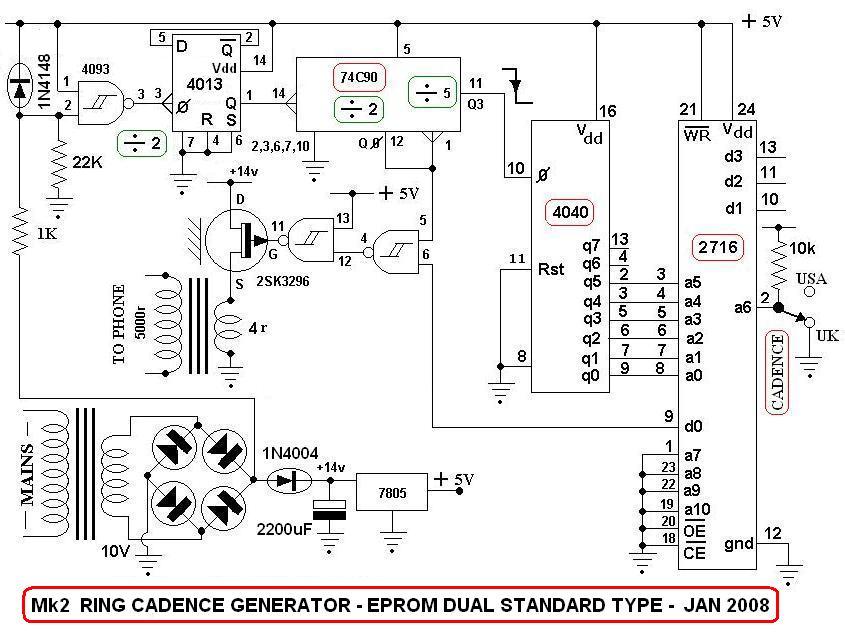
This is a switch-selectable dual output version of a previous design from 2007, utilizing a field-programmed EPROM to generate two versions of the ringing sequence. The AC mains voltage is stepped down to approximately 10 V AC and then...
This application note describes the implementation of a single-supply triangular wave oscillator using the MAX9000 integrated circuit and several passive components. The circuit employs an operational amplifier, a comparator, and a voltage reference as the main active components. The...
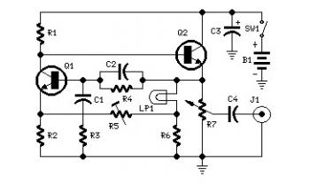
Set R5 to read 1V RMS on an audio millivoltmeter connected to the output with R7 rotated fully clockwise, or to view a sine wave of 2.828V peak-to-peak amplitude on the oscilloscope. An audio amplifier is an electronic device...
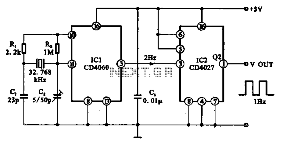
A 1Hz clock signal generator circuit is presented, which demonstrates a sophisticated clock signal generating mechanism. This circuit can be utilized for digital clocks and timing applications. It comprises a binary counter (CD4060), a JK flip-flop (CD4027), and a...
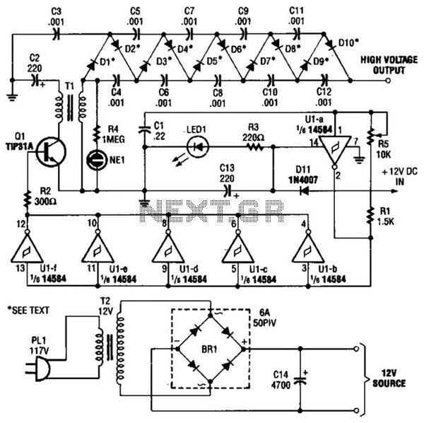
In the miniature high-voltage DC generator, the circuit receives input from a 12 V DC power supply, which is amplified to produce a 10,000 V DC output. This process induces a pulsating signal of opposite polarity in the secondary...
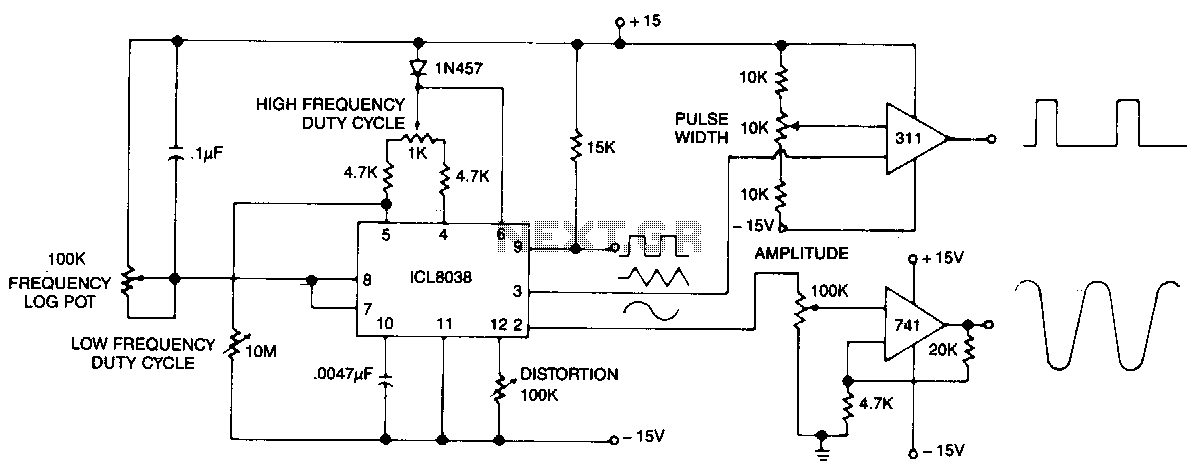
This circuit generates sinusoidal, square, and triangle waveforms simultaneously. The frequency can be set to a specific value or varied as indicated. An operational amplifier can be added for enhanced drive capability and simplified amplitude adjustment. Additionally, a simple...