
1KHz Sinewave Generators
The inverted Wien bridge oscillator is a well-regarded circuit for generating sine waves with low distortion and high stability. In this configuration, capacitors C1 and C2, along with resistors R3 and R4, form the frequency-determining network. The frequency of oscillation is primarily set by the values of these resistors and capacitors, allowing for precise tuning of the output frequency to 1 kHz.
The variable output feature is achieved through the use of a potentiometer or variable resistor (R5), which allows for adjustment of the amplitude of the output sine wave. Low distortion is maintained through careful selection of the components and the feedback mechanism, which ensures that the output closely resembles a true sine wave.
The low output impedance characteristic of the circuit is crucial for driving loads effectively without significant voltage drop, which is particularly important when interfacing with measurement equipment such as audio millivolmeters or power meters. The circuit's design incorporates a small filament lamp, which serves as a thermal feedback element. This lamp stabilizes the amplitude of the output waveform by providing a consistent load that compensates for variations in output voltage.
For practical application, the circuit can be calibrated by adjusting R5, allowing for a reading of 1V RMS on an audio millivoltmeter connected to the output. When R7 is set fully clockwise, this configuration enables observation of a sine wave with a peak-to-peak voltage of 2.828V on an oscilloscope, facilitating accurate testing and analysis of audio circuits. This versatility makes the inverted Wien bridge oscillator an essential tool for audio engineers and technicians.This circuit generates a good 1KHz sinewave using the inverted Wien bridge configuration (C1-R3 & C2-R4). Features a variable output, low distortion and low output impedance in order to obtain good overload capability.
A small filament lamp ensures a stable long term output amplitude waveform. Useful to test the Audio Millivoltmeter, Audio Power M eter and other audio circuits published in this site. Set R5 to read 1V RMS on an Audio Millivoltmeter connected to the output with R7 fully clockwise, or to view a sinewave of 2. 828V Peak-to-Peak on the oscilloscope. 🔗 External reference
Related Circuits
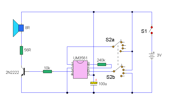
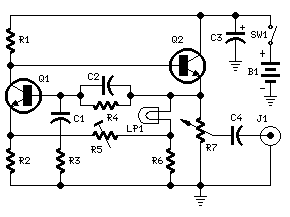
The integrated circuit (IC) generates various sound effects, with the output at Pin 3 amplified by a transistor. A 64-ohm loudspeaker can replace the 56-ohm resistor and 8-ohm loudspeaker. A two-pole, four-way switch controls the sound effects, with position...
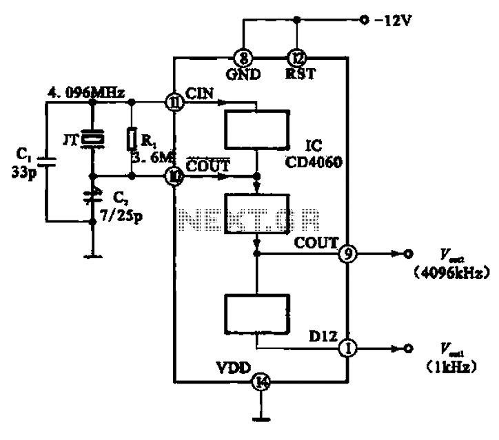
A 1 kHz square wave signal source circuit is illustrated using the CD4060 integrated circuit. The CD4060 operates with an external crystal oscillator and compensating capacitors such as C1 and C2. The internal oscillator circuit of the chip is...
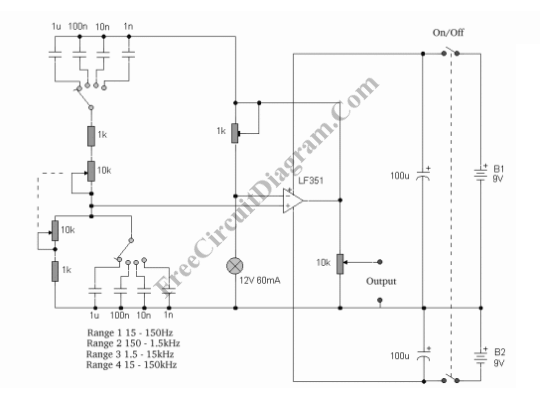
This sine wave generator is adjustable between 15 Hz and 150 kHz. The circuit is essentially a Wien-bridge oscillator, featuring multiple capacitor selections. The sine wave generator operates on the principle of the Wien-bridge oscillator, which is known for producing...
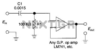
This simple 1 kHz filter utilizes a voltage follower and an RC section as its filtering element. For other frequencies, the -3 dB point is given by the formula 1/(6.28 Rl Cv), and the response decreases at a rate...
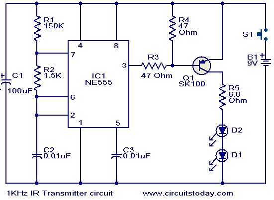
This circuit was designed in response to a request for a 1 kHz infrared (IR) transmitter circuit suitable for remote control applications. It is intended to serve as a low-power IR transmitter with an operating frequency of 1 kHz,...

Generators that do not use fuel to operate provide 24 hours of electricity for continuous use. In the early days of this invention, a significant issue arose: the battery powering the generators would deplete within 20 to 30 minutes...