
1N5401 3.0 AMP Silicon Rectifier

The circuit design begins with a power transformer that converts the mains voltage (240V) to a lower voltage (36V) suitable for the amplifiers. The center-tapped configuration allows for the generation of both +25V and -25V outputs, creating a dual power supply necessary for the operation of the stereo amplifiers. The rectification process employs four 1N5401 diodes arranged in a full-wave bridge configuration. This setup ensures efficient conversion of the alternating current (AC) from the transformer into direct current (DC), providing a stable power supply.
The circuit also features a current detection mechanism. When the current consumption exceeds 5 mA, a signal lamp is illuminated, indicating that the amplifiers are drawing power. The design incorporates diodes D1 and D2, which are capable of handling higher current loads, thus ensuring reliability and durability under varying operational conditions. The transistor T1 plays a critical role in this circuit; it is activated by the voltage drop across D1 and D2, enabling further control over the circuit's functionality.
Additionally, the voltage regulation is managed by the 78xx series regulators, which are known for their robustness and ease of use. These regulators typically provide a maximum output current between 1A and 1.5A. For applications requiring higher current outputs, modifications to the circuit can be made to accommodate additional components or configurations that enhance the current capacity.
The components listed in the parts list are crucial for the circuit's operation. Resistors R1 and R2, with a value of 4.7 kΩ each, are used for current limiting and biasing purposes. Capacitors C1 and C2, rated at 4700 µF / 16V, serve to smooth the rectified output, while C3, with a higher capacitance of 47,000 µF / 35V, provides additional filtering to ensure a stable DC voltage. The diodes, rated at 3 Amps, are robust enough to handle the expected current loads, ensuring the reliability of the power supply circuit within the audio amplification system.The schematic below shows how the +25V DC and -25V DC are obtained. In order to provide power supply for 2 stereo amplifiers, a power transformer rating of 80VA with 240V/36V centre tapped secondary winding is used. The secondary output of the transformer is rectified by using four 1N5401 diodes toge. The circuit in Fig. 56-11a lights the signal la mp upon detecting a line current consumption of more than 5 mA, and handles currents of several amperes with appropriate diodes fitted in the Dl and D2 positions. Transistor T1 is switched on when the drop across D1/D2 exceeds a certain level. Diodes fr. By default, the regulator ID 78xx series will give maximum current output 1A – 1. 5A. To increase the current output of this regulator, you may consider this circuit. Parts list:R1, R2 = 4. 7 KC1, C2 = 4700 uF / 16VC3 = 47, 000 uF / 35VD1, D2, D3 = 1N5401 ( 3 Amp Diodes )D4 & D5 –. 🔗 External reference
Related Circuits
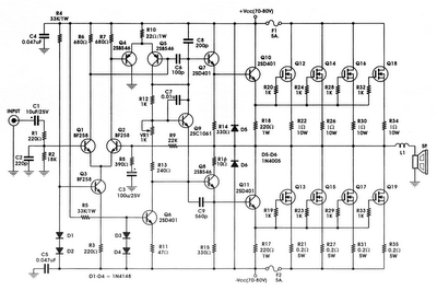
The circuit incorporates components Q, C, and ZD, which are responsible for the bias and buffer stages. Its primary objective is to ensure stable MOSFET gate operation and provide an offset voltage through a voltage buffer amplifier stage with...
This is a simple microphone preamplifier circuit that can be used between a microphone and a stereo amplifier. This circuit is suitable for connection with standard home stereo amplifier line/CD/aux/tape inputs. The microphone preamp can accommodate both dynamic and...
This is a very simple, low cost, Hi-Fi quality power amplifier. You can build it 5 ways, like it is shown in the table (from 20 W to 80 W RMS). The first thing that you must do, is...
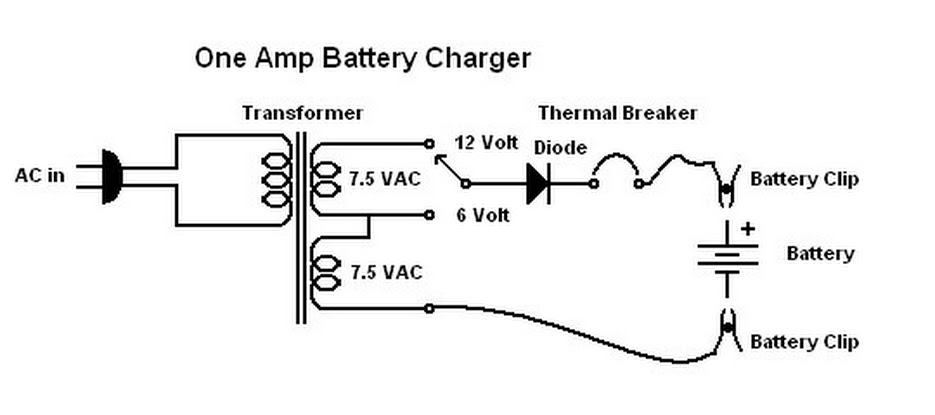
When this battery charger was purchased in 1970, it was not anticipated that it would still be relevant today. At that time, the owner had an old car with a weak battery that struggled to start in cold weather,...

A simple linear voltage-controlled amplifier can be constructed with one operational amplifier (op amp) and two junction field-effect transistors (JFETs). This amplifier can achieve an 80-dB dynamic control range with less than ±0.2% linearity error for 0 V. The described...

The air sampler is a highly effective multi-stage wetted-wall cyclone that continuously processes air at a rate of 325 liters per minute, extracting particulates and transferring them to a liquid phase with a volume of 4 to 5 cc....