
Op Amp And Two JFETs Form A Voltage-Controlled Amplifier

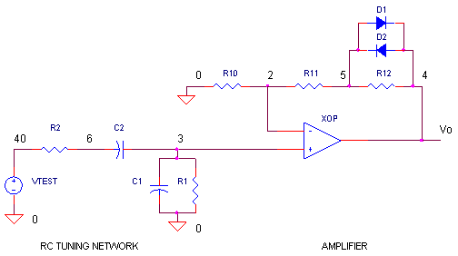
The described circuit utilizes a single op amp in conjunction with two JFETs to create a voltage-controlled amplifier (VCA) that operates efficiently within a specified dynamic range. The operational amplifier serves as the core component for signal amplification and control, while the JFETs function as variable resistors, modulated by an input control voltage.
In this configuration, the op amp is typically connected in a non-inverting configuration to ensure that the output maintains the same phase as the input signal. The two JFETs are arranged in a manner that allows for the adjustment of the gain based on the control voltage applied to their gates. This setup enables the amplifier to provide a wide dynamic control range of 80 dB, making it suitable for applications requiring precise amplitude control.
The linearity error of less than ±0.2% indicates that the amplifier maintains a high degree of fidelity across its operational range, which is critical for audio and signal processing applications. The low distortion ensures that the output closely resembles the input signal, barring the amplification factor.
In terms of implementation, careful selection of the op amp and JFETs is essential to achieve the desired performance characteristics. The op amp should have a high slew rate and low noise to minimize signal degradation. The JFETs must be chosen based on their transconductance and threshold voltage to ensure they operate effectively within the linear region throughout the control voltage range.
Overall, this linear voltage-controlled amplifier design offers a robust solution for applications that require precise control over signal amplification while maintaining high linearity and low distortion.A simple linear voltage-controlled amplifier can be constructed with one op amp and two JFETs (see the figure). The amplifier can achieve an 80-dB dynamic control range with less than ±0.2% linearity error for 0 V .
🔗 External reference
Related Circuits
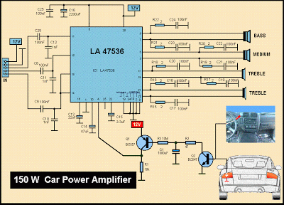
This is a diagram of a car audio active loudspeaker utilizing the LF353 operational amplifier from National Semiconductor. For optimal performance, the NE5532 is recommended to split the audio signal into three frequency bands using an active filter. The...
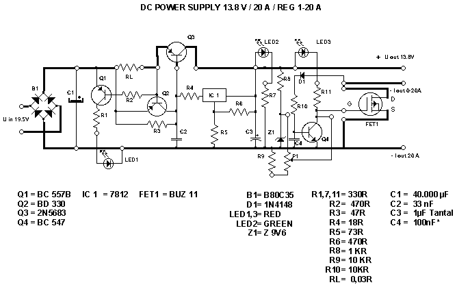
This PSU has been especially designed for current-hungry ham radio transceivers. It delivers safely around 20Amps at 13.8V. For lower currents, a separate current limiting output, capable of 15ma up to a total of 20A has been added. The...
The operational amplifier Wien-bridge oscillator offers insight into classic oscillator design through feedback analysis. Feedback analysis determines whether a circuit is stable or unstable. In amplifier design, particularly for high-speed applications, avoiding conditions that lead to oscillation is crucial....
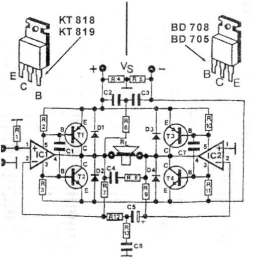
This audio amplifier circuit provides up to 200 W of high-quality output for loudspeakers with impedances ranging from 4 to 16 ohms. The operating voltage is between 24 and 36 V, with a maximum current of 5 A. The audio...
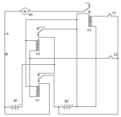
The simplest of all motor controllers (besides a straight on/off switch) is the contactor controller. Aaron designed this contactor controller for use in his electric scooter project. It is based around three 12V relays, two 12V batteries, two switches...
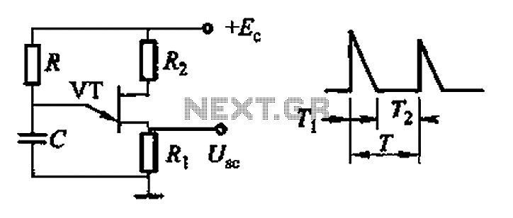
Common non-sinusoidal oscillator circuit, waveform and frequency formula - pulse wave oscillator - blocking oscillator transformer The common non-sinusoidal oscillator circuit is designed to generate pulse waveforms, which are characterized by their square or rectangular shape. These oscillators are...