
1W Long Range FM Transmitter
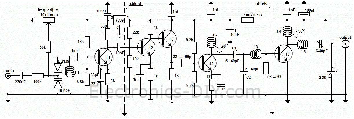
The T2 and T3 transistors serve as buffer stages, with T2 functioning as a voltage amplifier and T3 as a current amplifier. This buffer stage is crucial for frequency stabilization, acting as a buffer between the oscillator and the preamplifier and final amplifier. Poorly designed transmitters often experience frequency shifts when adjusting the final stage; however, the inclusion of T2 and T3 mitigates this issue. T4 acts as a preamplifier for the FM transmitter, serving as a voltage power RF amplifier that provides sufficient power to the final T5 transistor. A capacitor trimmer is included in T4's collector to create a resonance circuit that enhances amplification while eliminating unwanted harmonics. Coils L2 and L3 must be oriented at 90 degrees to each other to prevent frequency and parasitic coupling.
The final stage of the transmitter utilizes any RF power transistor capable of at least 1 watt output power. Suitable transistors include 2N3866, 2N4427, 2N3553, BLX65, KT920A, 2N3375, BLY81, 2SC1970, or 2SC1971 for optimal performance. Using a 2N2219 will yield a maximum output of 400 mW. A suitable heatsink is recommended for the T5 transistor, as it may generate heat during operation. A stabilized power supply of at least 12V/1A is necessary.
Construction begins with the oscillator stage. A small wire should be soldered to the output of T1's 10pF capacitor, allowing for tuning via an FM receiver. The 10K potentiometer should be adjusted until a blank noise or audio signal is heard. With a 70 cm wire, the oscillator stage alone can cover a distance of 2 to 3 meters. After completing the transmitter assembly, an antenna or a 50 or 75-ohm resistive load should be connected. Using an RF probe, or a 1N4148 diode as an alternative, the 10K potentiometer should be readjusted to the desired frequency. The trimmer in T4's collector should be adjusted for maximum voltage indication on a multimeter, followed by adjustments of subsequent trimmers. This process may require multiple iterations to achieve the highest voltage reading.
To achieve 1 watt RF power, a voltage measurement between 12 to 16 volts is expected. The RF power can be calculated using the formula P (in watts) = U² / Z, where Z is 150 for a 75-ohm resistor or 100 for a 50-ohm resistor, noting that the actual RF power is typically lower. Following these adjustments, the antenna can be connected, and further readjustment of all trimmers, starting from T3, should be performed while monitoring for harmonics. It is essential to check for interference on nearby TV and radio sets in a separate room to ensure compliance with operational standards.Long range, very stable, harmonic free, FM transmitter circuit which can be used for FM frequencies between 88 and 108 MHz. With good antenna transmitter can cover 5km range. It has a very stable oscillator because it uses LM7809 voltage regulator which is a 9V stabilized power supply for T1 transistor.
Frequency adjustment is achieved by using th e 10K linear potentiometer. The output power of this long range RF transmitter is around 1W but can be higher if you use transistors like KT920A, BLX65, BLY81, 2N3553, 2SC1970 or 2SC1971. T1 is used as an oscillator stage to deliver a low power stable frequency. To adjust the freq. use the 10k linear potentiometer like this: if you trim down, towards ground, the freq. will drop and if you adjust it toward + it will rise. Basically the potentiometer is used as a variable power supply for the two BB139 varicap diodes. Those two diodes act like a variable capacitor when you adjust the pot. By varying the diode capacitance the L1 + diodes circuit makes a resonance circuit for T1. You can use transistors like BF199, BF214 but do not use BCs. At this moment you don`t have yet the long range fm transmitter because the power is quite low, no more than 0.
5 mW. T2 and T3 works as a buffer stage, T2 as a voltage amplifier and T3 as a current amp. This buffer stage is very important for freq stabilization because is a tampon circuit between the oscillator and the preamp and final amplifier. It is well known that poor transmitter designs tend to modify freq. as you adjust the final stage. With this T2, T3 stage this won`t happen anymore! T4 is a preamplifier for the FM transmitter and is used as a voltage power RF amplifier and will deliver enough power to the final T5 transistor.
As you can see T4 has a capacitor trimmer in its collector, this is used to make a resonance circuit that will force T4 to amplify better and get rid of those unwanted harmonics. L2 and L3 coils must be at 90 degrees angle one to another, this is to avoid frequency and parasite coupling.
The final stage of the long range RF transmitter is equipped with any RF power transistor that has at least 1 watt output power. Use transistors like 2N3866, 2N4427, 2N3553, BLX65, KT920A, 2N3375, BLY81, 2SC1970 or 2SC1971 if you want to have a pro FM transmitter with enough power to cover a long range area.
If you use 2N2219 you will get no more than 400mW. Use a good heatsink for the T5 transistor as it gets a little hot. Use a good 12V/1Amp minimum stabilized power supply. Start by construction the oscillator stage, solder a small wire to T1 10pF capacitor out and listening to a FM receiver, trim the 10k pot until you can hear a blank noise or if you plug in an audio source you can hear the music. With a 70cm wire you can cover a 2 3 meter area just with the oscillator stage. Then continue to build the rest of the RF transmitter, use proper shielding as indicated in the circuit schematic.
When you finished the transmitter construction connect the antenna or better a 50 or 75 © resistive load and use this RF probe, you can use 1N4148 diode instead of the probe diode. Adjust again the 10k pot to desired freq. and then go to T4 stage and trim the first collector trimmer for maximum voltage indication on the multimeter.
Then continue with the next trimmer and so on. Then go back to the first trimmer and readjust again until you obtain the highest voltage on the multimeter. For 1 watt RF power you can measure a 12 to 16 Voltage. The formula is P (in watt) is equal to U2 / Z, where Z is 150 for 75 © resistor or 100 for 50 © resistor, but you must remember that the real RF power is lower.
After those adjustment, if everything is going well connect the antenna, continue using the RF probe, readjust again all the trimmers starting from T3. Make sure you don`t have harmonics, check your TV and radio set to see if there is disturbance on the band.
Check this in another room, far 🔗 External reference
Related Circuits
This circuit represents a conventional Colpitts type crystal oscillator, where the output is taken from a low-value collector load resistor. Direct coupling is implemented into the base of a PNP transistor used as an amplifier, resulting in a simplified...
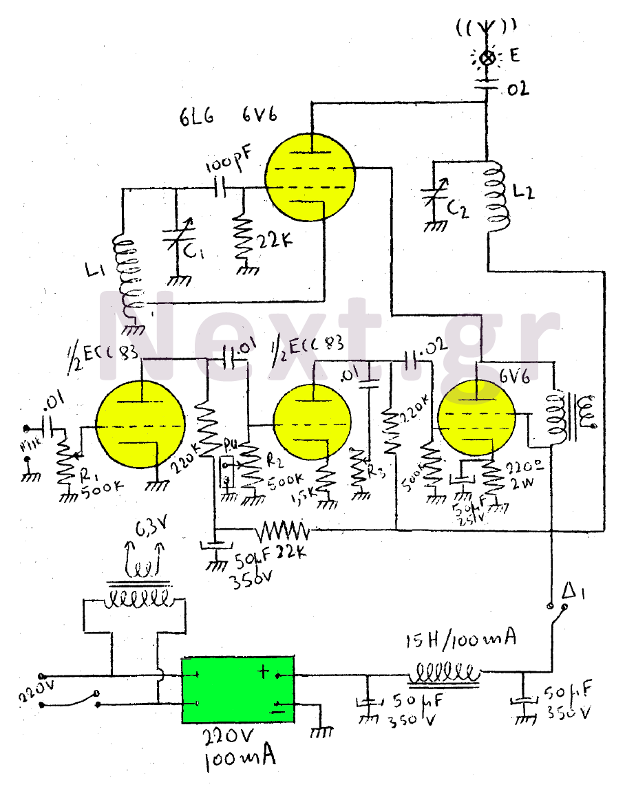
This circuit features a wearer assembly that includes a single lamp, either a 6V6 or 6L6, functioning as both an oscillator and an output amplifier. Coil L1 serves as the medium wave oscillation coil, while coil L2 is composed...
The current loop interface is widely used in industrial environments due to its robustness. Its noise resistance and failure detection capabilities make it suitable for various applications. The current loop interface, commonly referred to as a 4-20 mA current loop,...
The first resistor on the left in the schematic is labeled as 68k. This value may change based on the microphone used. In this instance, a microphone from Digi-Key with a 1.5k output impedance was utilized, leading to the...
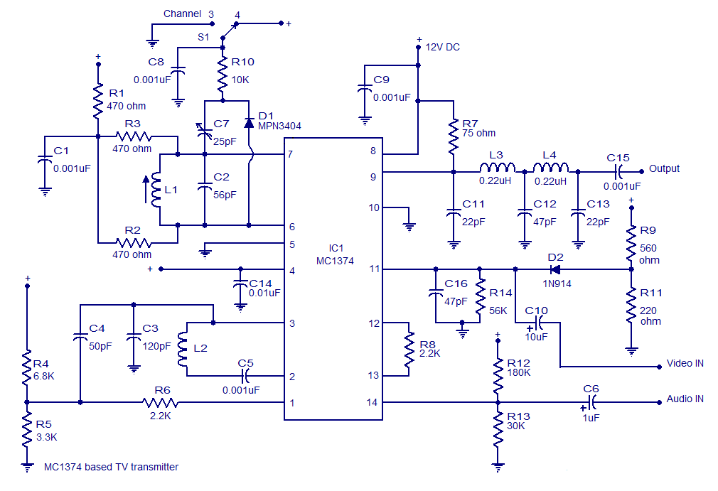
A very simple and high-quality TV transmitter circuit based on the IC MC1374 is presented in this article. The MC1374 is an integrated TV modulator circuit suitable for various TV transmitter applications. It encompasses all necessary circuitry required for...
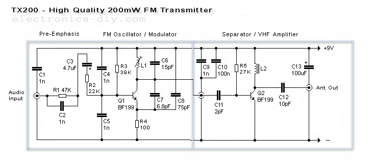
The TX200 is an advanced and significantly larger VFO/VCO FM transmitter, recognized as one of the best transmitters available. It is a 200mW FM transmitter designed for stereo PLL applications, providing a wide range for broadcasting music throughout a...