
1W Mono Amplifier with TDA7052 circuit diagram
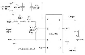
The audio amplifier circuit utilizing the TDA7052 is designed for low-power audio amplification applications. The TDA7052 is a monolithic integrated circuit that offers high-quality audio output with minimal external components, making it suitable for battery-operated devices. The circuit typically includes passive components such as resistors and capacitors that assist in signal filtering, gain adjustment, and stability.
The power supply voltage range of 6-12V allows for versatility in various applications, including portable audio devices, small radios, and other consumer electronics. The absence of a heatsink is a significant advantage, as it simplifies the design and reduces the overall size and weight of the circuit. This characteristic is particularly beneficial in compact applications where space is limited.
In the schematic, the TDA7052 will be connected to the power supply through appropriate decoupling capacitors to ensure stable operation. Input audio signals will be fed into the amplifier via coupling capacitors, which block any DC offset and allow only the AC audio signal to pass through. Feedback resistors may be used to set the gain of the amplifier, ensuring that the output level meets the desired specifications without distortion.
Additionally, the output stage of the TDA7052 is designed to drive small speakers directly, providing sufficient power to deliver clear sound reproduction. The circuit may also include bypass capacitors at the power supply pins to filter out noise and improve the overall performance of the amplifier. Overall, this audio amplifier circuit is an efficient and straightforward solution for enhancing audio output in various electronic devices.This is anaudioamplifier circuit which use TDA7052 as the main component and other 5 pieces of components to support the main component. The ideal supply voltage of this circuit is about 6-12V and no heatsink required. 🔗 External reference
Related Circuits
The described shunt-feedback configuration facilitates the straightforward incorporation of frequency-dependent networks, enabling a practical and unobtrusive switchable tilt control as an optional feature. When switch SW1 is in the first position, a gentle shelving bass boost and treble cut...
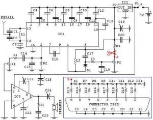
This is an FM radio receiver circuit that can be used with a PC. The circuit includes several regulations: A) The P1 potentiometer is used to adjust the sound intensity. B) The P2 potentiometer is used to adjust the...
This circuit is designed to support nine independent telephones using a single telephone line pair, allowing for operation at nine different locations. It includes a bidirectional telephone line simulator that does not require actual telephone lines, enabling the coupling,...
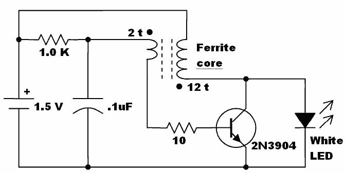
Here is an idea for a voltage booster that enables the lighting of a white LED using a single AA cell. This presents an opportunity to utilize one of the ferrite cores and white LED holiday lights mentioned in...
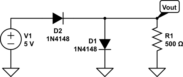
The two diodes will fail. It is advisable to include series resistors for them. If the simulation is successful, the current through the diodes will be excessive. Both diodes do not necessarily need to fail; one may become a...
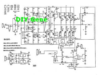
The following circuit illustrates a complete solid-state M-9 power amplifier circuit diagram. Features include a DC servo that acts as a loudspeaker protection circuit. The solid-state M-9 power amplifier circuit is designed to deliver high-quality audio amplification while ensuring the...
Warning: include(partials/cookie-banner.php): Failed to open stream: Permission denied in /var/www/html/nextgr/view-circuit.php on line 713
Warning: include(): Failed opening 'partials/cookie-banner.php' for inclusion (include_path='.:/usr/share/php') in /var/www/html/nextgr/view-circuit.php on line 713