
1Watt AM CW Transmitter for 10 Meterband

This circuit design provides a practical approach to building a low-power AM transmitter suitable for educational purposes and hobbyist experimentation. The integration of a crystal oscillator ensures frequency stability, which is crucial for minimizing interference and maintaining a clear transmission. The use of a Colpitts oscillator configuration is advantageous due to its simplicity and effectiveness in generating high-frequency signals. The choice of transistors, such as the BSX20 for the oscillator and the BD135 for amplification, reflects a balance between performance and availability, making this circuit accessible to a wide range of builders.
Incorporating a low-frequency preamplifier stage is particularly beneficial when using dynamic microphones, as it enhances the microphone's output to a sufficient level for effective transmission. The inclusion of filtering stages, such as the L-filter and low-pass PI filter, is essential for refining the output signal, reducing unwanted harmonics, and ensuring compliance with spectral purity standards. This attention to detail in signal processing is critical for achieving a quality transmission that can be received clearly by AM radio receivers.
Overall, this project exemplifies fundamental radio transmission principles and offers a hands-on opportunity to explore the intricacies of electronic circuit design and radio frequency communication. Proper attention to licensing regulations and safety practices is recommended when operating any transmission equipment.In this project, you will make a simple 3-stage low-power broadcast-type circuit, using a crystal oscillator integrated circuit and an a collector modulated AM oscillator with amplifier. You can connect the circuit to the an electred microphone or amplified dynamic microphone. Using an electred microphone is shown (in gray) in the diagram below. (no amplified dynamic microphone has a to low output voltage to work. at least 100mv is needed). You could also add a LF preamp stage of one transistor to allow connecting a dynamic microphone directly.
You`ll see that you can receive the signal through the air with almost any AM radio receiver. Although the circuits used in radio stations for AM receiving are far more complicated, this nevertheless gives a basic idea of the concept behind a principle transmitter. Plus it is a lot of fun when you actually have it working! Remember that transmitting on the 10 meter band you`ll need a valid radioamateur license!! A wide range of different circuits have been used for AM, but one of the simplest circuits uses collector modulation applied via (for example) a transformer, while it is perfectly possible to create good designs using solid-state electronics as I applied here (T1 BC557).
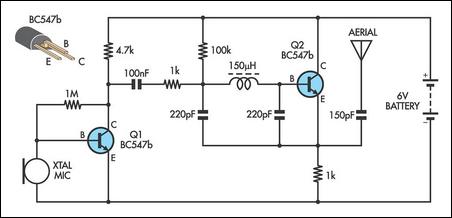
The transmitter is build as a Colpitts Oscillator with a BSX20 transistor. HF-output of the oscillator is approx. 50 mW, depending on the supply voltage of 6 to 15 Volts. This is amplified by the BD135 and brings the power up to approx. 1 watt @ 12volts. The transmit frequency is stabilized with the 28Mhz crystal. A slight detuning of approx 1kc is possible when using a 120pF trimmer capacitor for C8. The oscillator signal is taken from the collector of T2 and guided to the input of T3 which output is lead via an L-filter and low-pass PII filter circuit cleaning up the signal pretty good and ensuring spectral purity. The oscillator is keyed by T1 and the morse key (S). By keying the morse-key T1 is not been used for modulation and is biased, hence lets T2 freely oscillate.
🔗 External reference
Related Circuits
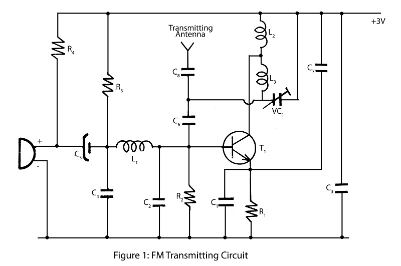
A simple and powerful FM transmitter is an interesting project that utilizes one transistor and operates within a frequency range of 100 MHz. The circuit diagram includes a description of the FM transmitter and various related interesting projects. The FM...

The three schematics illustrate three building blocks for a 10-meter SSB transmitter. These blocks can also be utilized independently as circuit modules for other transmitters. The VFO board incorporates an FET transmission oscillator, with the VFO signal being mixed...
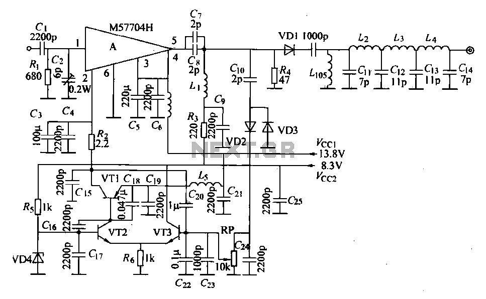
The FM radio transmitter is a high-frequency amplifier circuit that utilizes the Mitsubishi frequency set, specifically the M57704H discharge path. It operates within the frequency range of 457-458 MHz and has a transmission power of 5 watts. As illustrated...
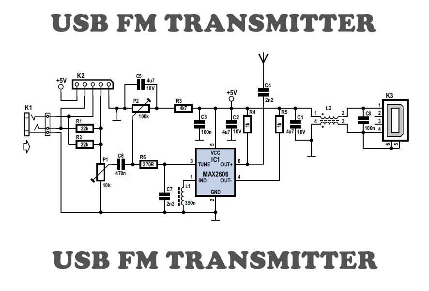
To test VHF receivers independently from local radio stations, a frequency-modulated oscillator is required, covering the range of 89.5 to 108 MHz. Building such an oscillator with discrete components is challenging. The MAX260x series from Maxim offers five integrated...
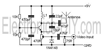
This is a simple video transmitter capable of transmitting signals up to 50 meters. It can be connected to a camera or other video sources, allowing viewing on a VHF channel analog TV. The transmitter operates on a supply...
This AM transmitter is designed for simplicity, featuring a non-tapped inductor with a single winding. The inductor is a standard RF choke, such as the Jaycar Cat LF-1536, eliminating the need for custom winding. To minimize the circuit's size,...
Warning: include(partials/cookie-banner.php): Failed to open stream: Permission denied in /var/www/html/nextgr/view-circuit.php on line 713
Warning: include(): Failed opening 'partials/cookie-banner.php' for inclusion (include_path='.:/usr/share/php') in /var/www/html/nextgr/view-circuit.php on line 713