
SG3525 PWM DC Motor Circuit

The circuit utilizes a pulse-width modulation (PWM) technique to regulate the speed and torque of DC motors. The fundamental principle behind PWM is the adjustment of the duty cycle of the voltage applied to the motor. By varying the width of the pulses, the average voltage and current supplied to the motor can be effectively controlled, allowing for smooth operation and enhanced efficiency.
Key components of the circuit include a microcontroller or a PWM generator, a power transistor or MOSFET, and the DC motor itself. The microcontroller generates a PWM signal, which is then fed into the gate of the power transistor. When the PWM signal is high, the transistor conducts, allowing current to flow to the motor. Conversely, when the PWM signal is low, the transistor turns off, interrupting the current flow.
To ensure accurate control, the circuit may include feedback mechanisms, such as encoders or tachometers, which monitor the motor's speed and position. This feedback is processed by the microcontroller to adjust the PWM signal dynamically, maintaining the desired performance parameters.
Additional components such as diodes may be included for flyback protection, safeguarding the circuit from voltage spikes generated by the inductive load of the motor. Capacitors might also be employed to smooth out the voltage supply and reduce electrical noise, further enhancing the stability of the control system.
Overall, this circuit diagram is an effective solution for achieving precise and efficient control of DC motors in various applications, including robotics, conveyor systems, and automotive systems.The Circuit diagram is ideal for accurate control of DC motors. DC voltage conversion to a series of pulses, such that the duration of the pulse .. 🔗 External reference
Related Circuits
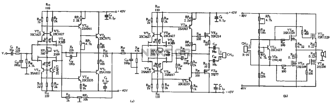
The circuit design features a unique technology and a reasonable structure utilizing all-discrete components with a Class A FET output. The complete circuit includes an input stage, an output stage, and a power level circuit to enhance performance, along...

This circuit is straightforward and well-defined. The transmitter operates at 9 volts, while the receiver circuit functions at 5 volts. The transmitter utilizes a 555 timer and two SL100 transistors to perform its function. The receiver incorporates a small...
This DIY magnetic field sensor circuit is straightforward and capable of detecting both fixed magnetic fields and those that vary at audio frequencies. The device is not designed for precise measurement of magnetic field strength. A small and relatively...
Incorporate a straightforward, economical jack-sensing circuit (JACKSENSE) into a DirectDrive automotive headphone amplifier to detect when headphones are plugged into the audio jack. The implementation of a jack-sensing circuit (JACKSENSE) in a DirectDrive automotive headphone amplifier is designed to enhance...
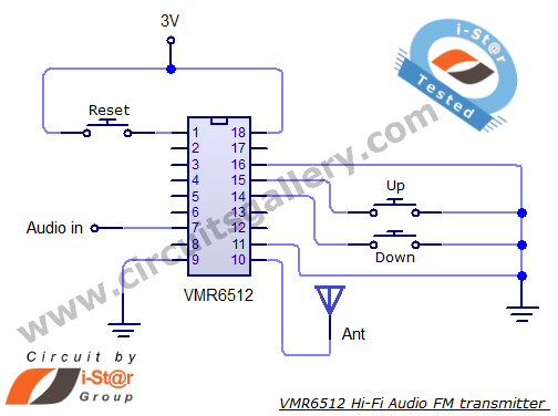
This article provides the circuit schematics for an FM transmitter along with the necessary explanations. The primary component utilized is the VMR6512 IC, a highly integrated FM audio signal transmitter chip designed for Hi-Fi audio applications. This chip can...
The metal detector consists of a probe oscillator, a reference oscillator, an audio amplifier, and various other components, as illustrated in the schematic. The probe oscillator is made up of transistors V1 and V2, a detection coil L1, a...