
2 lines FET Audio Mixer
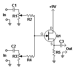
This circuit operates by combining multiple audio signals into a single output, effectively allowing for the mixing of stereo signals into a mono output or the combination of multiple audio sources. The design utilizes operational amplifiers (op-amps) configured as summing amplifiers, which provide a low-impedance output suitable for driving subsequent stages or loads.
The basic structure includes multiple input sections, each consisting of an input resistor connected to the inverting terminal of an op-amp. The non-inverting terminal is typically grounded. The feedback resistor from the output to the inverting terminal sets the gain of the op-amp, allowing for control over the mixing levels of the individual channels. By adjusting the values of the resistors, the circuit can be fine-tuned to achieve the desired balance among the mixed signals.
For applications requiring more than two inputs, the design can be expanded by simply replicating the input sections. Each additional channel is connected in the same manner, ensuring that all inputs are summed at the op-amp's inverting terminal. This modular approach allows for a flexible number of inputs, accommodating various audio mixing needs.
Power consumption is minimal, making this circuit suitable for battery-operated devices or applications where energy efficiency is critical. It is advisable to enclose the circuit in a shielded case to minimize electromagnetic interference (EMI) and ensure high-quality audio output. Proper grounding and layout considerations should be taken into account to prevent noise and distortion in the mixed signal. Overall, this mixer circuit is a versatile solution for audio applications requiring signal combination.This simple circuit mixes two or more channels into one channel (eg. stereo into mono). The circuit can mix as many or as few channels as you like and consumes very little power. The mixer is shown with two inputs, but you can add as many as you want by just duplicating the "sections" which are clearly visible on the schematic. 1. As many or as few channels as are required can be added to the mixer. Do this by just duplicating the input "sections" which are clearly shown on the schematic. One version of this mixer I saw had 25 inputs! 2. A shielded case is probably 🔗 External reference
Related Circuits
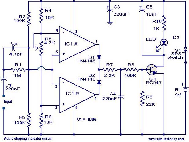
This circuit is designed to detect clipping in a specific waveform. Clipping occurs when the amplitude of a waveform decreases before reaching its expected limit. The circuit activates an LED as an indication that the tested signal is experiencing...
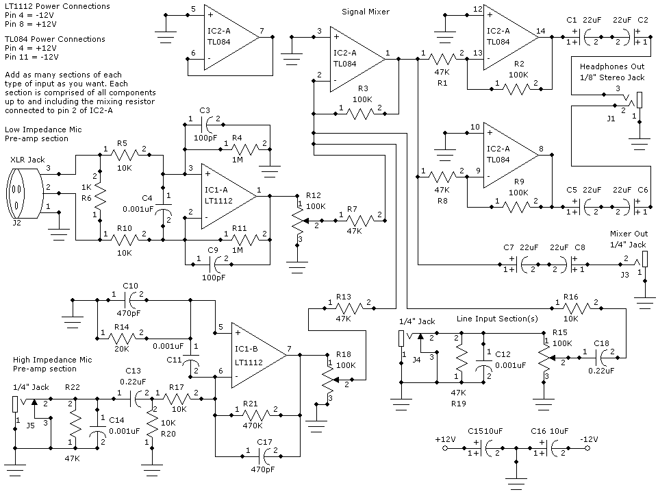
This weblog focuses on electronic circuit schematics, PCB design, DIY kits, and diagrams for various electronic projects. It features a mixer that demonstrates how to create microphone pre-amplifiers suitable for both low and high impedance microphones. The design utilizes...
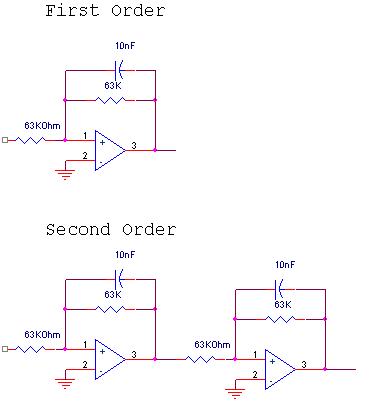
The circuit design involves a circular operational amplifier (op-amp) configuration that functions as a second-order low-pass and high-pass filter. The low-pass filter operates within a frequency range of 20 to 250 Hz, while details regarding the high-pass filter are...
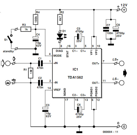
The integrated output amplifier presented in this article consists primarily of a single integrated circuit. It is specifically designed for application in motor vehicles and other battery-operated devices. Despite its seemingly simple design, the amplifier is capable of delivering...
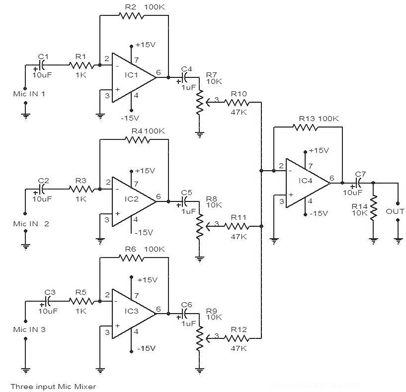
This is a circuit diagram of a 741 IC-based three-input microphone mixer circuit. A total of four 741 ICs are utilized, with IC1, IC2, and IC3 serving specific functions within the design. The circuit utilizes four operational amplifiers from the...
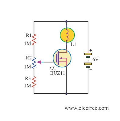
Changing the value of R2 alters the intensity of the lamp in this circuit, demonstrating the utility of a MOSFET as a variable resistor. An N-Channel Power MOSFET, designated as Q1, is utilized in the circuit. The specific part...