2-Pin Automobile Indicator Lamp Flasher Circuit with Buzzer
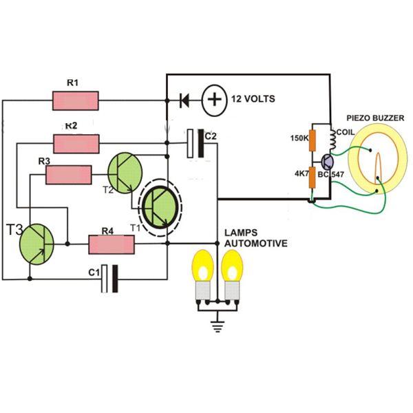
This circuit is designed to create a flasher unit for a motorbike. It is a simple turn signal flasher circuit that can be easily built and installed in any two-wheeler for the desired functionality. The circuit uses only two pins instead of three, which are commonly found in other flasher circuits. Once installed, the circuit will reliably flash the side indicator lights whenever the intended function is activated. Additionally, the circuit includes an optional buzzer that can be incorporated to provide a beeping sound in response to the flashing of the lamps.
The motorbike flasher circuit operates primarily on the principle of an astable multivibrator configuration, typically utilizing a 555 timer IC or a similar timing component. The circuit consists of a power supply, which may be derived from the motorbike's battery, ensuring compatibility with the vehicle's electrical system. The two pins mentioned correspond to the input and output terminals that connect to the turn signal lights.
The flashing rate can be adjusted by varying the resistance and capacitance values in the timing circuit, allowing customization of the blink frequency to meet user preferences or legal requirements. This flexibility is particularly advantageous for different motorcycle models and user needs.
Incorporating the optional buzzer requires an additional transistor or relay to handle the current required by the buzzer, ensuring that it does not interfere with the operation of the indicator lights. When the turn signal is activated, the circuit not only flashes the indicator lights but also triggers the buzzer, providing an audible alert that complements the visual signal.
The design should include protective components such as diodes to prevent back EMF from damaging the circuit when inductive loads are switched. Additionally, proper heat dissipation measures may be necessary if the circuit components operate near their maximum ratings. Overall, this flasher unit offers a compact, efficient solution for enhancing the visibility and safety of motorbike turn signals.If you want to make a flasher unit for you motorbike then this circuit is just for you. This simple turn signal flasher circuit can be easily built and installed in any two wheelers for the desired actions. The circuit employs just two 2-pins instead of 3 as found in other flasher circuits. Once installed, the circuit will faithfully flash the sid e indicator lights whenever the intended function is switched ON. The circuit also incorporates an optional buzzer circuit which can be also included for getting a beeping sound in response to the flashing of the lamps. 🔗 External reference
