
Press light switch double circuit 4
The double touch lamp circuit operates on the principle of capacitive sensing, where the human body acts as a conductor. When a user touches the electrode sheets M1 or M2, a change in capacitance is detected, generating a signal that is processed by the time base circuit. The time base circuit is responsible for timing the duration for which the lamp remains on after the initial touch.
The circuit features two key diodes, VD2 and VD3, which serve to rectify the induced signals. VD2 is critical for converting the AC signal generated by the touch into a usable DC signal for triggering the time base circuit. VD3 performs a similar function for the off command, ensuring that the system can accurately detect when the user intends to turn off the lamp.
Relay K is a crucial component in this design, acting as the switch that controls power to the lamp. The choice of relay, such as the JZC-22F, is significant due to its compact size and capability to handle the DC load required for the lamp. The circuit design must also incorporate safety features, including appropriately rated resistors and capacitors to withstand the high voltage of the AC mains.
The circuit layout must ensure that the phase and neutral connections are correctly configured to prevent malfunction or safety hazards. Proper grounding and insulation are essential to ensure user safety and the reliable performance of the circuit. The inclusion of high-quality components, such as metal film resistors, enhances the overall reliability and longevity of the circuit, reducing the risk of failure due to heat or electrical stress.
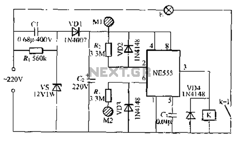
Overall, the design of this double touch lamp circuit combines simplicity with functionality, providing an innovative solution for user-friendly lamp control while adhering to safety and performance standards.A use NF, double touch lamp ~ 55 base circuit made of switches. 2ZOV AC by [1-, c:, VDI, vs simple composition of a single power save buck and a half crossing fetters flow regu lator circuit, but also through after C, resistant end-cho of about 1ZV about DC voltage for the time base tU Road electricity. Need to open the lamp, just plain hand touch the Refuse electrode sheet Ml, human induced noise signal after rectified by the VD2 gave time-based circuit trigger input terminal feet into a negative signal to the time base circuit set position, feet high output, relay K to their station suction units accounted for kl contact closure, Chan E electric powered light.
Turn off the lights when needed, just before touch - down beauty electrode sheet M2. Sense of human blood clutter signal rectified by VD3, the time base circuit threshold associative end pin input signal a coin, immediately reset the time base circuit output terminal lost thirty feet low, the relay K release, Chan E electrical flameout. (1. Requests resistant to E r is 400V and poly-ene capacitors, R, R. To use good quality high value resistor, such as metal film resistors will .K available JZC-22F, DC12V power in a small electromagnetic relay, the other element is the special requirements of their lC circuit with AC mains connection, lay phase, neutral position must be shown in Figure pjf, otherwise the circuit is not reliable work properly.
Related Circuits
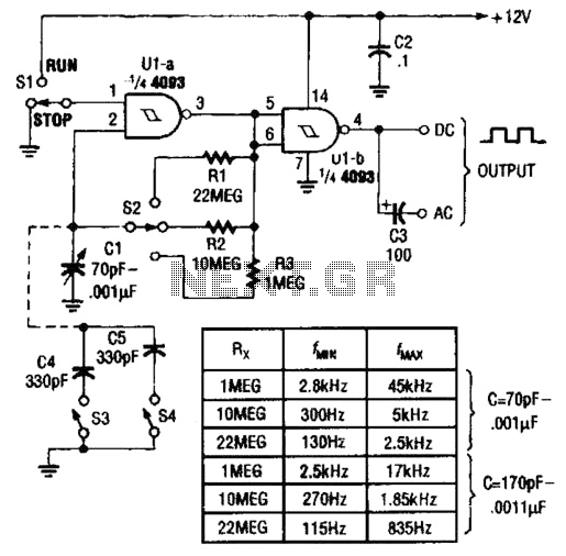
Two gates of a Quad 4093 are utilized in an astable multivibrator configuration. CI is a three-gang 365 pF variable capacitor with its sections connected in parallel. Additionally, S3 and S4 serve to switch in optional extra capacitors. The described...
The circuit below is a simple dimmer circuit. A network consisting of R1, R2, VR1, C2, C3, and Q1 controls the triggering angle of the triac by adjusting the variable resistor VR1. The described dimmer circuit employs a TRIAC (Q1)...
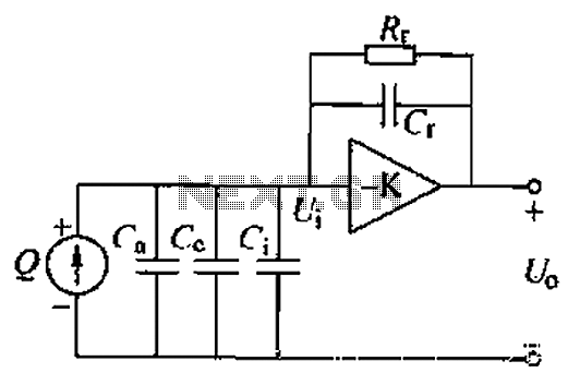
A charge amplifier is an effective device for measuring punch hits. This amplifier utilizes a negative feedback capacitor in conjunction with a high-gain operational amplifier. The amplifier operates with minimal shunt, relying primarily on the feedback capacitor's charge (q...
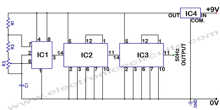
Accurate 50Hz Oscillator Circuit Using 555 and 7490. This circuit generates a 50Hz pulse. It consists of a 555 timer and two 7490 divide-by-ten counters. The circuit utilizes a 555 timer configured in astable mode to produce a square wave...
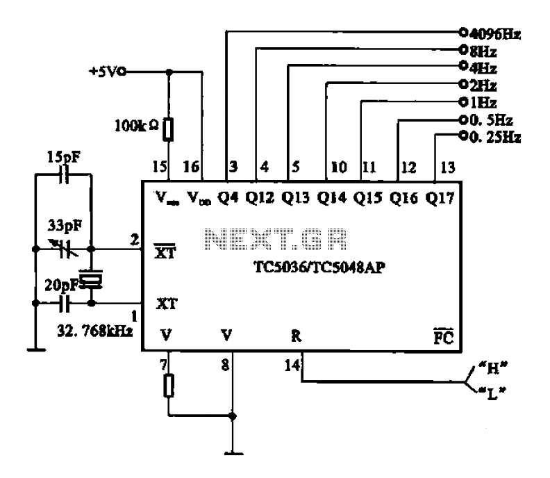
32.768 kHz; In MP3/MP4 devices, mobile phones, laptops, and other digital products, a real-time clock signal generating circuit is utilized, primarily composed of crystal resonators and TC5036/TC5048AP chip oscillators. This setup produces a raw 32.768 kHz crystal oscillator signal,...
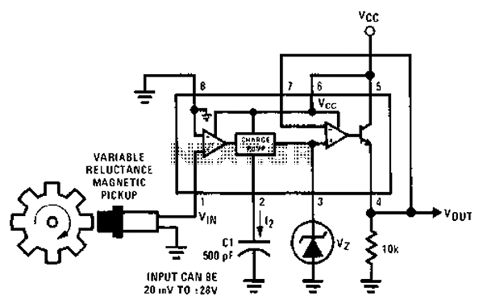
After each zero electromagnetic pickup receives a sine wave input, as illustrated in the National Semiconductor LM2907 circuit, it generates an output pulse. This circuit can be utilized in digital control systems. The width of each pulse corresponds to...