
tda7088t fm radio receiver circuit
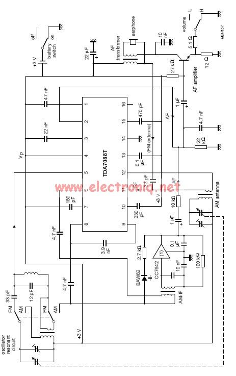
The TDA7088 is a highly integrated FM radio receiver IC designed to operate efficiently in low-power applications. The frequency-locked-loop (FLL) system is key to its operation, enabling the demodulation of FM signals while maintaining stability and accuracy in frequency selection. The Intermediate Frequency (IF) of approximately 70 kHz is chosen to optimize the performance of the receiver, allowing for effective filtering and amplification of the received signals.
Powering the TDA7088 can be achieved with a single 3-volt battery cell, making it suitable for portable devices where battery life is critical. Alternatively, a regulated power supply can be utilized to provide a stable voltage, ensuring consistent performance and reliability in various applications. The choice of power source may depend on the intended use case, whether it be in handheld devices, automotive applications, or stationary setups.
The design of the surrounding circuitry should include appropriate decoupling capacitors close to the power supply pins of the TDA7088 to minimize noise and ensure stable operation. Additionally, careful consideration should be given to the layout of the PCB to reduce interference and optimize the performance of the FLL system. Antenna selection and placement will also significantly affect the reception quality, necessitating the use of a suitable antenna design for the desired frequency range.
In summary, the TDA7088 is an efficient solution for FM reception in low-power applications, with its frequency-locked-loop system and flexible power options making it versatile for various electronic projects. Proper circuit design and component selection will enhance its performance, enabling effective signal processing in diverse environments.TDA7088 contains a frequency-locked-loop (FLL) system with an Intermediate Frequency (IF) of about 70 kHz. For supplying this circuit we can use an 3 volts battery cell or a regulated power supply. 🔗 External reference
Related Circuits
Here is a handy zener diode tester which tests zener diodes with breakdown voltages extending up to 120 volts. The main advantage of this circuit is that it works with a voltage as low as 6V DC and consumes...
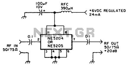
The Signetics NE5204 or NE5205 can be utilized in this audio frequency to 350-MHz (-30 dB) preamplifier. For a requirement of 600 MHz at 3 dB, the NE5205 should be employed. The noise figure is 4.8 dB at 75...
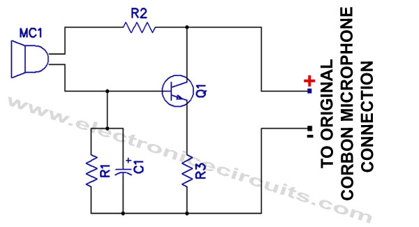
Effective pitching surpasses effective hitting, and a high-quality magnetic microphone outperforms a carbon microphone. This circuit utilizes a single transistor to convert a carbon microphone input into a magnetic microphone output. It is important to note that no ground...
Connect the two sections of the variable capacitor (C3) in series to linearize the tuning somewhat. Use the connections on either end of C3 and do not use the middle lead. The gain is sufficient to drive an earphone....
4V flat monitor high voltage power supply circuit diagram. A wide range of 7 to 40V to 5V DC-DC step-down circuit diagram. Light control switch circuit diagram for safety. Circuit 555 constitutes a control circuit diagram for photoelectric applications. The...
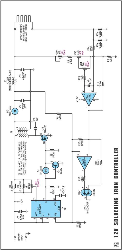
One reason commercial soldering stations are costly is that they typically require soldering irons with built-in temperature sensors, such as thermocouples. This circuit removes the necessity for a specialized sensor by detecting the temperature of a soldering iron heating...