
2 small magnification difference between the balanced output circuit
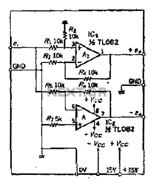
A balanced output configuration in operational amplifiers is crucial for minimizing noise and distortion, especially in high-frequency applications. The positive phase output terminal of the operational amplifier serves as the primary output, while the inverting input creates a phase-reversed output. This configuration is essential for differential signaling, where the goal is to maintain signal integrity over long distances.
In practical implementations, the inverting amplifier circuit can experience issues such as DC offset drift, which can compromise the balance of the output signal. This drift can be exacerbated in wide-band signal applications where the frequency response is critical. To mitigate these issues, circuit designers often incorporate feedback mechanisms and compensation techniques that stabilize the output against variations in input frequency.
The design of a balanced output circuit typically includes precision resistors and capacitors to ensure that the frequency response remains flat across the desired bandwidth. Additionally, careful consideration must be given to the layout of the circuit to minimize parasitic capacitance and inductance, which can introduce additional phase shifts and distortion.
Overall, maintaining a balanced output in operational amplifier circuits is vital for achieving high fidelity in signal transmission, particularly in audio and communication systems. The careful design and implementation of these circuits ensure that even with varying input conditions, the output remains stable and free from phase distortion.A balanced output mentioned, people tend to immediately think of the positive phase amplifier output terminal increases 0P amplifier as the inverting amplifier circuit, normal and reversed phase output set to lose balance fH o in the DC circuit, although this method can be used, but as Tiao are wide -band signal, the inverting amplifier cup drift is a problem. Since this circuit. OP measures also zoom in and drift d is equal to the soil, so even if the input frequency of change seven phase distortion does not occur 4
Related Circuits
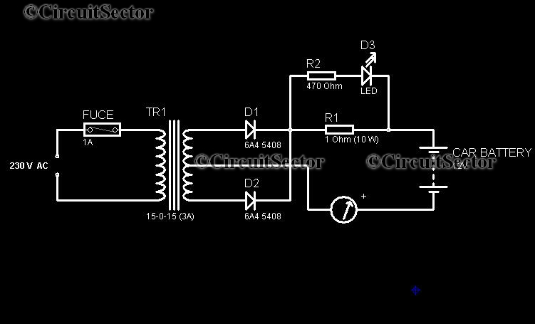
In today's world, owning a car battery charger at home has become essential. Having one readily available can help prevent starting issues caused by battery problems. While purchasing a commercial battery charger can be expensive, the components required for...
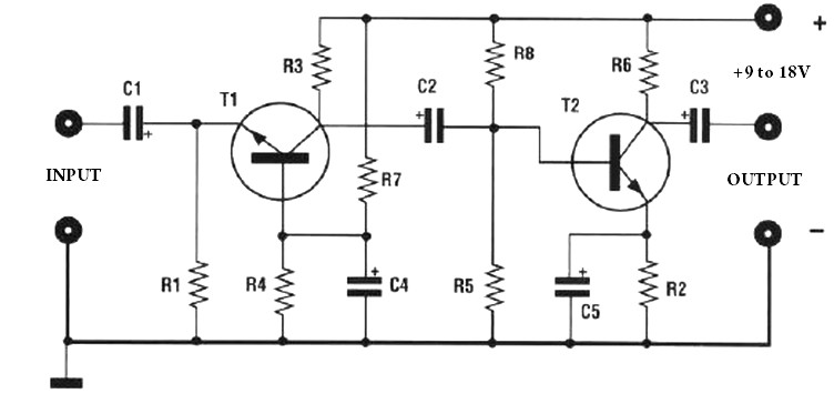
The amplification of this preamplifier is very high. To reduce the amplification, a trimmer resistor R3 in series with a value of 100 ohms should be used. The system can be powered by a voltage ranging from 9 to...
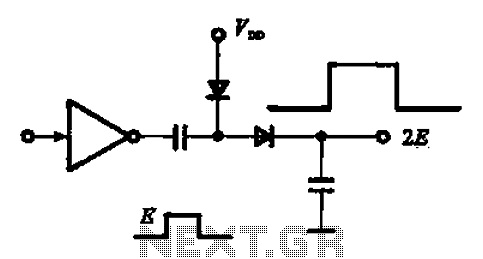
A pulse booster circuit is utilized to increase the pulse amplitude. The structure illustrated in figure (a) of the circuit can output a pulse amplitude that is twice that of the input. Figure (b) of the circuit can achieve...
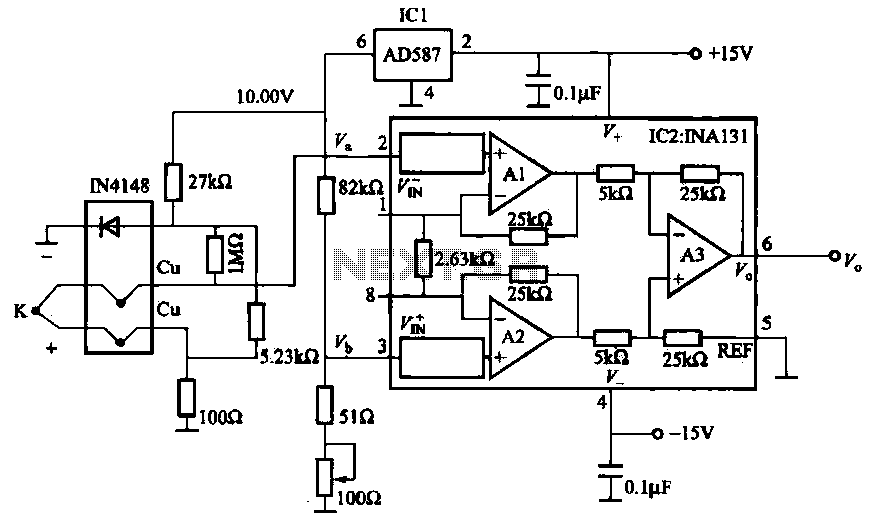
The AD587 is a precision voltage reference providing a 10 V output, generated using a 27 kΩ resistor along with a compensation diode (1N4148) and a thermocouple. This setup connects to the VI + N terminal of a differential...
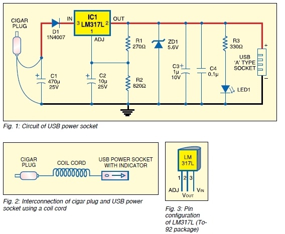
The safe 12V car adapter described here can be used to limit the current from a +12 volt car battery, available from the in-dash cigar lighter power port, to below 2.6A. The 12V car adapter is designed to ensure that...
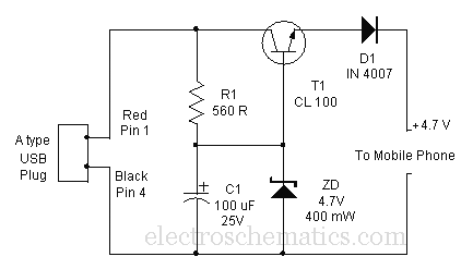
Comprehensive information about a USB cellphone charger circuit is available for learning and downloading online. The USB cellphone charger circuit is designed to convert AC mains voltage into a stable DC voltage suitable for charging mobile devices. This circuit typically...