
REMOTE TELEPHONE BELL RINGER

The telephone line extension bell ringer circuit is designed to enhance the functionality of traditional telephone systems by allowing the installation of remote ringers in locations where the ringing sound may not be heard. The circuit operates by utilizing the existing telephone line's voltage characteristics while ensuring that it does not interfere with normal telephone operations.
The core components of the circuit include a bridge rectifier, capacitors, resistors, neon lamps, a triac, and an optoisolator. The bridge rectifier is essential for converting the AC signal from the telephone line into a usable DC voltage, which is then filtered to provide a stable supply for the subsequent components. The neon lamps serve a dual purpose: they provide isolation from the telephone line and act as voltage indicators by ionizing at higher voltages, which is critical for detecting ringing signals.
The use of a capacitor (C1) to block DC voltage is crucial in preventing any DC bias from affecting the operation of the downstream components. The MOV acts as a protective element, ensuring that any unwanted voltage spikes from dialing pulses do not damage the circuit. The resistors (R1 and R2) and capacitors (C2 and C3) form a filter network that smooths out the rectified voltage, providing a clean signal to the transistor (Q1) for reliable operation.
The optoisolator serves to separate the control circuit from the high-voltage section, providing safety and preventing any feedback that could disrupt normal telephone operations. The triac acts as a switch that controls the power to the remote bell, allowing it to ring in response to the signaling from the telephone line.
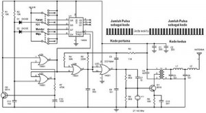
Overall, this circuit is a practical solution for enhancing telephone accessibility, particularly for individuals with hearing impairments, while maintaining compatibility with existing telephone infrastructure. Its design allows for flexibility in placement and functionality, making it a versatile addition to any home or office environment.The telephone-line extension bell ringer shown will enable you to add a remote ringer in your garage or some other area where a ringing telephone cannot be heard Up to Four ringers can be used on a single telephone line and a remote bell can be used 100 feet or more away from the unit By substituting a light bulb for T2 and dispensing with th e bell the circuit can be made useful for the hearing-impaired About 50 to 60 V dc is present between the tip and ring (red and green) wires of an unoccupied telephone line Capacitor C1 blocks that dc voltage The MOV just shunts any dialing pulses generated by a rotary phone that might be on the same line To make the phone ring the tip and ring wires deliver an ac signal of between 90 and 130 V to the phone That ac signal is coupled through C1 to the neon lamps NE1 and NE2 Those neon bulbs provide line isolation between the unit and the telephone line. They also neon fire (ionize) when more than 100 V is present on the phone line (in other words, during the ring signal).
When they fire, they form a three-step voltage divider with the bridge rectifier. The voltage across the bridge is rectified, then filtered by R1, R2, C2, and C3, and causes Q1 to conduct. Then pins 2 and 6 of U1 go low, causing pin 3 of U1 to go high. The optoisolator and triac then turn on, applying power to the remote bell through a doorbell transformer (T2).
🔗 External reference
Related Circuits
This infrared (IR) remote extender enhances the range of most basic IR remotes operating at a 40KHz modulation frequency significantly. When in operation, the remote is aimed at the detector on the circuit, and a button is pressed. The...
The following circuit illustrates a schematic diagram for a remote control toy car. Features: it does not affect the performance of the original design. The remote control toy car schematic circuit diagram typically consists of several key components that work...

This is a circuit design for a doorbell that produces a sound resembling that of a bird. The circuit is controlled by an NPN transistor. The operation begins when P1 is set to an experimental value, starting with approximately...
This circuit utilizes a synthesized sound chip from Holtek, the HT-2811, which produces the sound of a "ding-dong" chiming doorbell. Additionally, it incorporates a CMOS 4026 counter display driver integrated circuit (IC) to tally the number of visitors. The...
Replacing the resistor/transistor with an n-channel power MOSFET and substituting the relay/protection diode with a light bulb results in a simplified circuit that mirrors the original design, provided one end of the light bulb is connected to +12V. If...
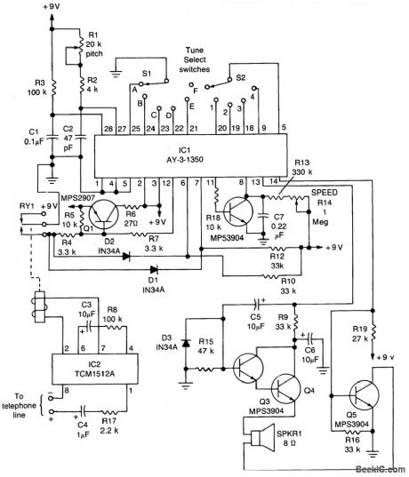
The core component of the circuit is IC1, the AY-3-1350 melody synthesizer IC from General Instrument. IC2 is a TCM1512 telephone ring detector IC powered by the telephone line. The circuit operates when IC2 detects a ring pulse on...