
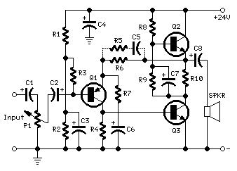
The Transistor Amplifier

Transistors play a pivotal role in electronic circuits, serving as switches and amplifiers. The NPN transistor operates by allowing current to flow from the collector to the emitter when a sufficient voltage is applied to the base. In contrast, the PNP transistor allows current to flow from the emitter to the collector when the base is at a lower voltage than the emitter. The choice between NPN and PNP transistors often depends on the specific application and circuit configuration.
In practical applications, understanding the parameters of transistors, such as the current gain (β), is crucial. The current gain defines the ratio of output current to input current, influencing the amplification ability of the transistor. Moreover, the operating point, determined by the biasing resistors, is essential for ensuring linearity in amplification and minimizing distortion.
The use of capacitors in conjunction with transistors helps to stabilize the DC operating point while allowing AC signals to pass through, effectively decoupling different stages of the circuit. This is particularly important in multi-stage amplifiers where each stage must operate independently without interference from others.
In conclusion, while transistors are fundamental components in electronic circuits, their proper implementation requires an understanding of their characteristics and the surrounding circuitry. The interplay of resistors, capacitors, and the configuration of the transistor itself determines the overall performance and functionality of the circuit.Time would be much better spent on explaining transistor and MOSFET behaviour in a simpler way and getting on with digital circuitry and microcontroller projects. You simply cannot put a transistor into a circuit and expect it to produce the calculated results. The gain of a transistor can be from 100 to 200 in a batch and this changes the outcome by 50%! There are thousands of transistors and hundreds of different makes, styles and sizes of this amazing device. But there are only two different types. NPN and PNP. The most common is NPN and we will cover it first. There are many different styles but we will use the smallest and cheapest. It is called a GENERAL PURPOSE TRANSISTOR. The type-numbers on the transistor will change according to the country where it was made or sold but the actual capabilities are the SAME.
It is also referred to as a BJT (Bi-polar Junction Transistor) to identify it from all the other types of transistors (such Field Effect, Uni-junction, SCR, ) but we will just call it a TRANSISTOR. Most small transistors have a plastic case and the leads are in a single line. The side of the transistor has a "front" or "face" with markings such as transistor-type. Fig 10 has a capacitor on the input and output. This means the stage is separated from anything before it and anything after it as far as the DC voltages are concerned and the transistor will produce its own operating point via the base resistor and LOAD resistor.
We have already explained that the value of the two resistors should be chosen so the voltage on the collector should be half-rail voltage and this is called the "idle" or "standing" or "quiescent" conditions. When the voltage on the collector is mid-rail, the transistor can be turned off a small amount and turned on a small amount and the voltage on the collector will fall and rise.
(note the FALL and RISE). Fig 11 shows a small waveform on the input and a large waveform on the output. The increase in size is due to the amplification of the transistor. A stage like this will have an amplification of about 70. This is called "Stage Gain" or "Amplification factor" and consists of two things. The output voltage will be higher than the input voltage and the output current will be higher than the input current. For example, if the incoming signal is rising, the collector voltage will drop and this will be passed through the base-bias resistor to deliver less current to the base.
This is opposing the current being delivered via the signal and that`s why it is called NEGATIVE EFFECT or NEGATIVE FEEDBACK. Thus the transistor cannot produce the output amplitude you are expecting. Fig 11a and 11b shows a Common Emitter stage with fixed base-bias. This stage produces the maximum voltage amplification but it is very difficult to "set-up" because the value of the base resistor will either make the collector voltage nearly zero or full rail voltage.
It is very difficult to get the collector to sit at mid rail. It is a "Class-C" stage and means it is just at the point of being turned on via the base-bias resistor. It consumes the least current when "sitting around" and is the most efficient stage. The output waveform will be distorted at the top or bottom, depending on the biasing and an inductor in the collector can reduce the distortion.
See the article on FM 🔗 External reference
Related Circuits
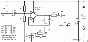
This is a simple stereo electret microphone preamplifier circuit. For optimal performance, it is recommended to use solid or film capacitors and metal film resistors. The circuit is based on a single IC, the LM358. It is straightforward, cost-effective,...
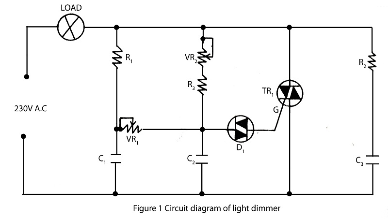
The lighting source, such as a bulb or tube light, illuminates based on its specified wattage. To achieve increased brightness, a higher wattage bulb must be used, while a lower wattage bulb is necessary for reduced brightness. However, it...
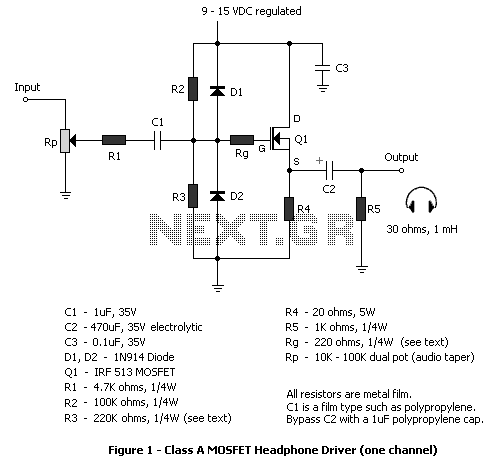
The circuit described in this article is a MOSFET follower for driving headphones. FET followers can supply high current, but have a voltage gain of slightly less than unity. They are most suitable in applications where the input signal...
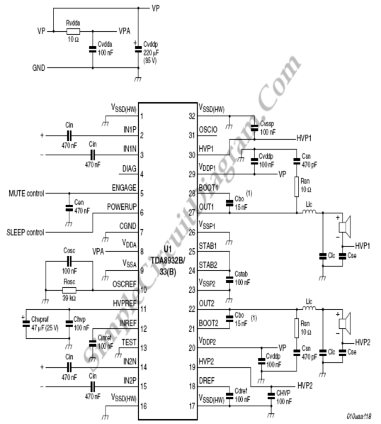
The following circuit diagram illustrates a simplified application circuit for the TDA8932B/33(B) device when it is powered by an asymmetrical supply (single supply). The TDA8932B/33(B) is a class-D audio amplifier integrated circuit designed for efficient audio amplification in various applications....
The philosophy behind this minimalist design has been explained by Flavio Dellepiane on his highly interesting site. I have myself written an article about this fleapower amp from Italy in the American magazine AudioXpress. All relevant details are published...
The preamplifier is designed for use with dynamic (moving coil, MC) microphones that have an impedance of up to 200 ohms and feature balanced terminals. It is relatively straightforward. The preamplifier circuit serves as a crucial interface between the microphone...