
2 watt amplifier tda7052

The 2-watt audio amplifier circuit utilizing the TDA7052 integrated circuit (IC) is designed for basic audio amplification applications. The TDA7052 is a low-voltage audio amplifier that can deliver up to 2 watts of output power, making it suitable for driving small speakers or headphones.
The circuit typically includes the following key components: the TDA7052 IC, a power supply, input capacitors, feedback resistors, and output capacitors. The power supply provides the necessary voltage for the IC, which usually operates within a range of 3V to 15V. The input signal is coupled to the amplifier through capacitors that block any DC offset, ensuring that only the AC audio signal is amplified.
Feedback resistors are incorporated to set the gain of the amplifier, allowing for adjustments based on the desired output level. The output stage of the circuit is connected to a load, such as a speaker, through output capacitors that filter out any unwanted DC components, ensuring that only the amplified audio signal reaches the speaker.
The TDA7052 is known for its simplicity and ease of use, requiring minimal external components to function effectively. It features built-in short-circuit protection and thermal shutdown capabilities, enhancing the reliability of the circuit. This audio amplifier circuit is ideal for applications in portable audio devices, small radios, or as a basic amplifier in DIY audio projects.
In summary, the 2-watt audio amplifier circuit using the TDA7052 IC is a straightforward and efficient solution for audio amplification, suitable for various low-power audio applications.Schematic diagram and description of 2 watt audio amplifier circuit using TDA7052 amplifier IC. This is a super simple audio amplifier circuit. .. 🔗 External reference
Related Circuits
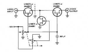
A variable gain amplifier controlled by voltage, functioning as a video amplifier. It utilizes three Field Effect Transistors (FETs) of type U1897E, which can be substituted with 2N4091. The described variable gain amplifier is designed to adjust its gain based...
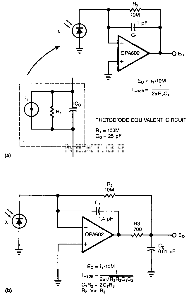
Adding two passive components to a standard photodiode amplifier reduces noise. Without the modification, the shunt capacitance of the photodiode reacting with the relatively large feedback resistor of the transimpedance (current-to-voltage) amplifier creates excessive noise gain. The improved circuit...
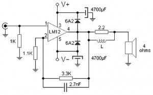
The 100W audio power amplifier is powered by the integrated circuit LM12CLK, which is an operational power amplifier. The 100W audio power amplifier utilizing the LM12CLK integrated circuit is designed to deliver high-quality audio output with significant power handling capabilities....
The Electronics Schematic Diagram MJR7-Mk3 Mosfet MJR6 page includes distortion extracted using the nulling method with a speaker load and a music signal to demonstrate that these designs have no audible distortion in normal use. The MJR7 has even...
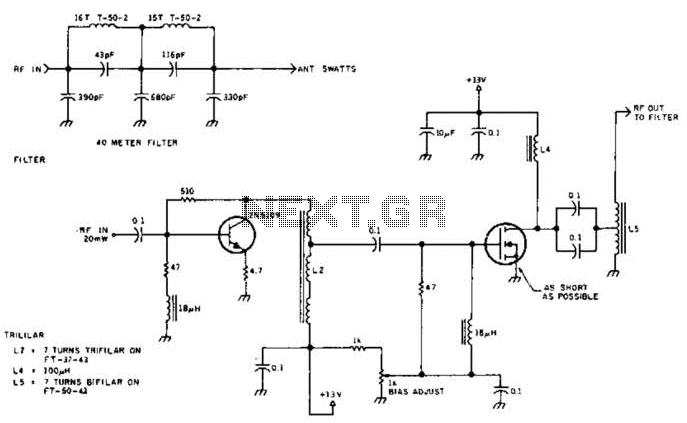
The circuit illustrated is designed to generate up to 5 watts of RF output in the 40-meter (7 MHz) amateur band. The coils depicted are wound on toroidal cores from Armdon Associates Inc., with part numbers provided in the...
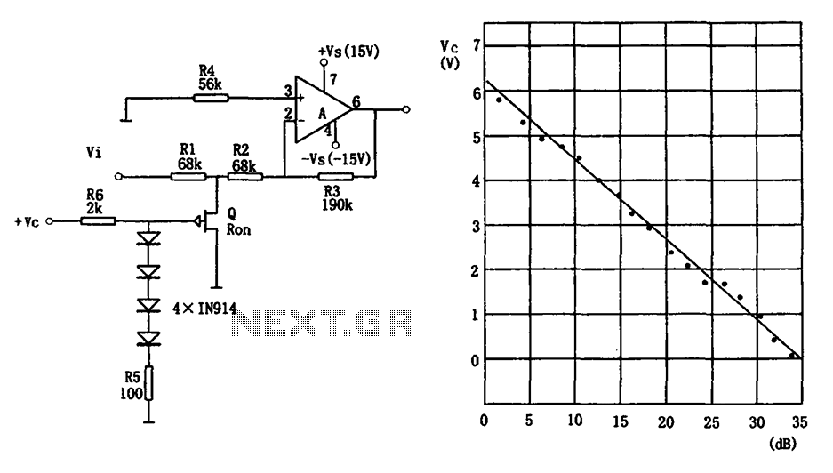
The voltage-controlled gain amplifier utilizes a FET gate voltage and the drain-source resistance (RSD) to approximate a logarithmic relationship. The integrated circuit chip LM307 is employed in the amplifier circuit with the inverting input configuration. In the circuit, RSD...