
accelerometer amplifier circuit

The accelerometer amplifier circuit is designed to accurately convert the charge output from a precision accelerometer into a usable voltage signal. This is crucial for applications where precise motion detection or orientation measurement is required. The circuit employs an inverting amplifier configuration, which is essential due to the nature of charge-output devices.
The operational amplifier used in this design is the LT1113, known for its low noise and high precision characteristics, making it suitable for sensitive applications. The capacitor C1 plays a critical role in the charge-to-voltage conversion process. It is important that C1 is selected to equal the sum of the transducer's capacitance and the input capacitance of the operational amplifier to ensure optimal performance.
The low-frequency bandwidth of the amplifier is determined by the product of R1 and C1, which dictates the response time of the amplifier to changes in input signal. In scenarios where a Tee network is implemented, the bandwidth can also be influenced by the resistive divider formed by R2 and R3. The noise gain of the circuit, defined as 1 + C1/CT, highlights the relationship between the feedback capacitance and the total capacitance in the circuit, which affects the overall stability and performance.
A critical aspect of the design is the time constant of the servo loop, represented by 1/R5C5. This time constant must be larger than that of the amplifier's time constant (1/R1C1) to ensure that the servo can adequately respond to changes without introducing instability or oscillation into the system. Proper selection of the resistors and capacitors in the circuit is therefore essential to maintain a balance between responsiveness and stability, ensuring that the accelerometer provides accurate readings in dynamic conditions.This is a circuit for accelerometer amplifier. This is a simple circuit. Precision accelerometer needs inverting mode amplifier since they are usually charge-output devices. This amplifier is convert charges into voltage output. The circuit below is an example of accelerometer with DC servo. This circuit built by IC LT1113. The charge from the tra nsducer is converted to a voltage by C1, which should equal the transducer capacitance plus the input capacitance of the op amp. The low frequency bandwidth of the amplifier will depend on the value of R1 C1 (or R1 (1 + R2/R3) for a Tee network).
The noise gain will be 1 + C1/CT. The time constant of the servo (1/R5C5) should be larger than the time constant of the amplifier (1/R1C1). 🔗 External reference
Related Circuits
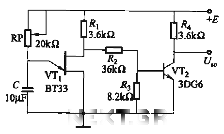
The circuit comprises a single-junction transistor VTi, a resistance Ri, a potentiometer RP, and a capacitor C, forming a relaxation oscillator and an amplifier transistor VTz. The adjustment potentiometer RP allows for changing the relaxation oscillation frequency, providing a...
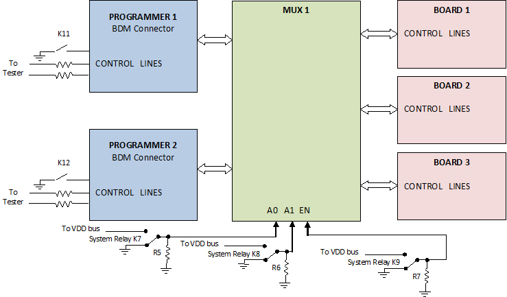
The use of programming pods has become a standard practice in manufacturing, particularly during the early development stages of firmware for new products. Once visual and structural tests are completed, the board is prepared for full functional testing. The...
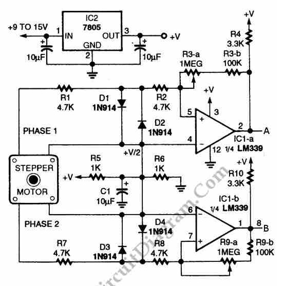
The circuit illustrated in the schematic diagram below allows for the visualization of the direction and shaft rotation of a stepper motor on an LED display. Instead of utilizing a digital rotation encoder as an input, this circuit employs...
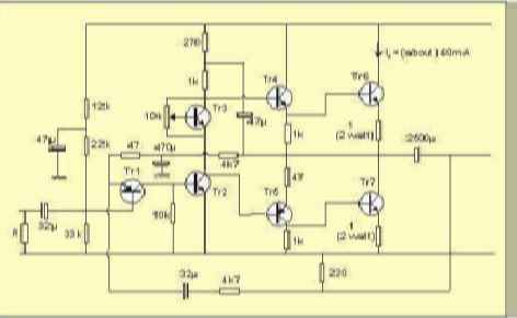
The table below illustrates the expected voltages when utilizing a 24V supply, with the variable resistor adjusted to provide an output current of approximately 40mA. The circuit operates with a 24V DC power supply, where a variable resistor (also known...
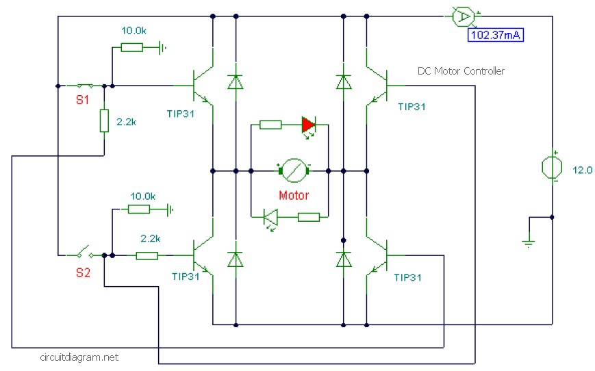
This is a DC motor controller circuit built using the TIP31 transistor based on the H-Bridge concept. The switches S1 and S2 are normally open, push-to-close buttons. The LED serves to indicate the direction of motor rotation and any...
This circuit can detect whether a train is in a particular drive. The output is TTL and CMOS compatible and can be processed by such a computer. The simple circuit works. The driving voltage is connected to the two...