
20 Khz ring counter
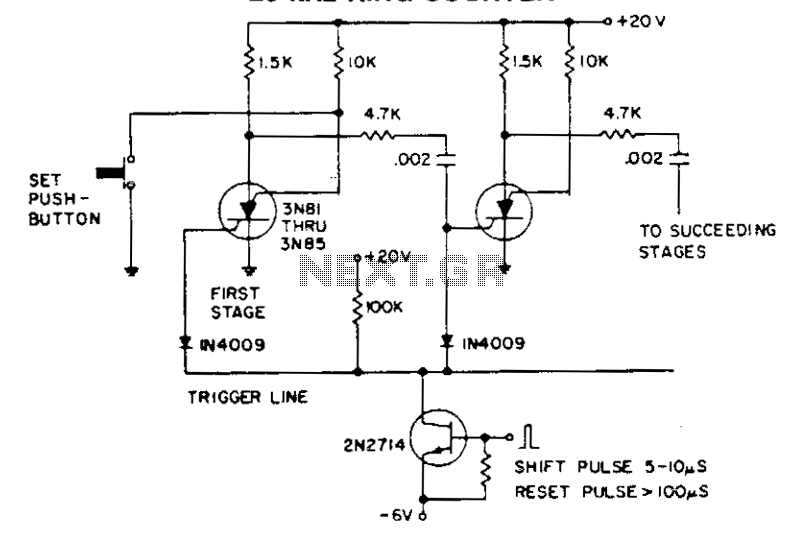
In a circuit utilizing silicon-controlled switches (SCS), the operation relies heavily on the timing and duration of the shift pulse. The shift pulse serves a critical function in controlling the state of the SCS by applying a reverse bias to the cathode gate. This reverse bias effectively turns off the SCS, halting current conduction through that particular switch.
The coupling capacitor plays a pivotal role in this process. Once the shift pulse is applied and the SCS is turned off, the charge stored in the coupling capacitor is released, which then acts as a trigger for the next stage of the circuit. This sequential triggering is essential for maintaining the operation of multi-stage circuits, where each stage must be activated in a controlled manner.
However, care must be taken regarding the duration of the shift pulse. If the pulse is too long, it can lead to an overcharging of the coupling capacitor and other capacitors in the circuit. This condition can inadvertently deactivate all stages, leading to a complete shutdown of the circuit’s functionality.
Additionally, grounding the anode gate of an SCS serves to "set" that stage. This action effectively prepares the stage for operation, allowing it to respond appropriately to subsequent control signals. The grounding mechanism is crucial for establishing a reference point in the circuit, ensuring that the SCS can be reliably activated or deactivated as required.
In summary, the interplay between the shift pulse, coupling capacitor, and grounding of the anode gate is fundamental to the operation of circuits utilizing SCS. Understanding these components and their interactions is essential for designing robust and reliable electronic systems.The shift pulse turns off the conducting scs by reverse biasing the cathode gate. The charge stored on the coupling capacitor then triggers the next stage. An excessively long shift pulse charges up all the capacitors, turning off all stages. Grounding an anode gate will "set" that stage. 🔗 External reference
Related Circuits
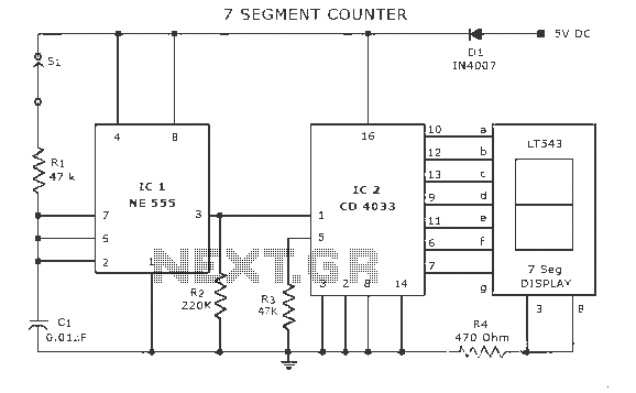
A display counter circuit is illustrated through a diagram featuring a seven-segment display controlled by the counter IC CD4033. This counter circuit is designed to visually represent incremental counts, enhancing its appeal for integration into various applications. An astable...
Using SimPLL's new PLL Wizard, a new Phase-Locked Loop (PLL) can be designed with just a few clicks. A PLL has been designed that tunes from 150 MHz to 170 MHz in 25 kHz steps, utilizing the LMX2306 PLL...
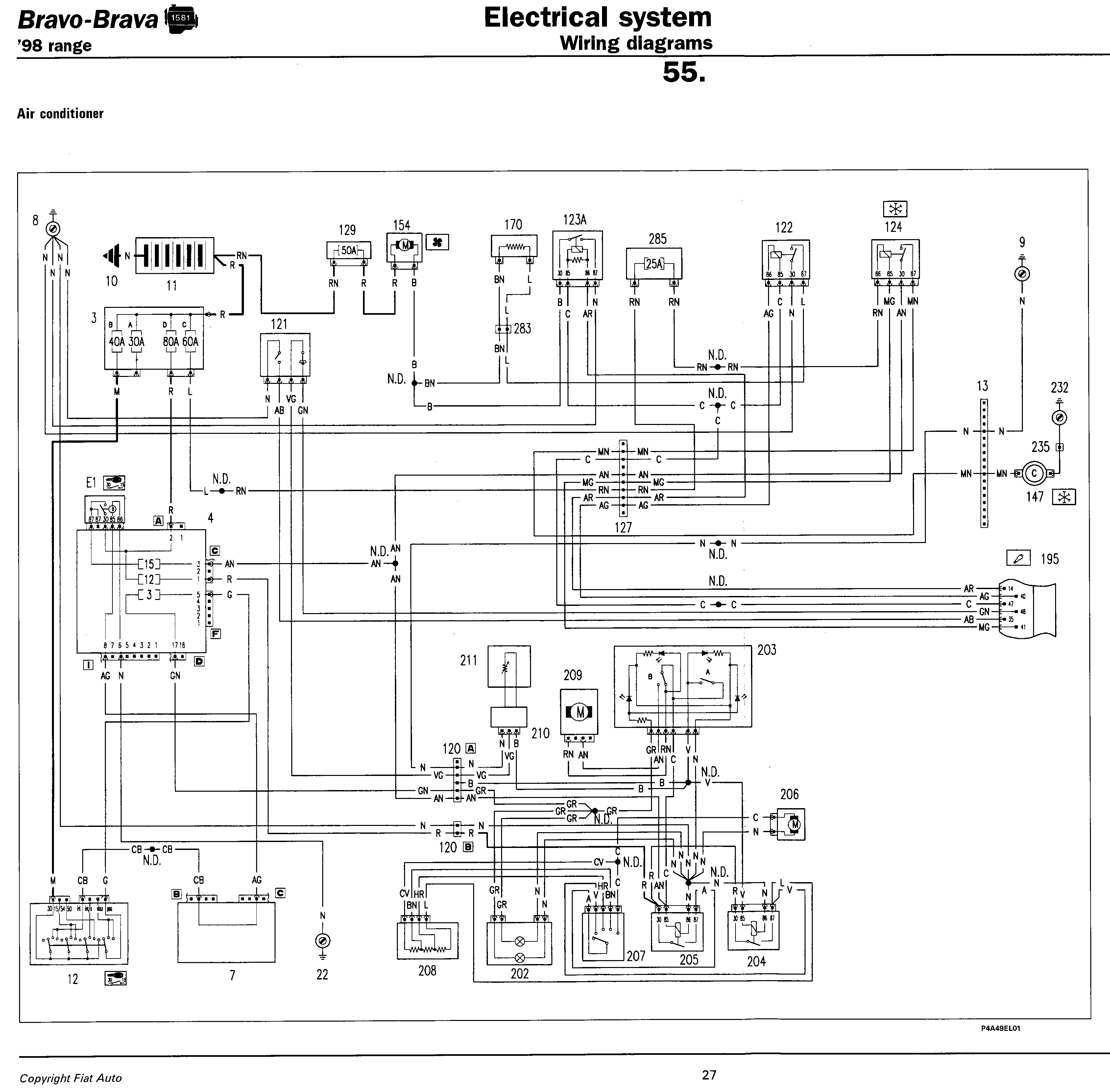
Fiat Punto Wiring Diagram Manual PDF Download. The Fiat Punto Wiring Diagram Manual provides essential information for understanding the electrical systems of the Fiat Punto model. This manual typically includes detailed wiring diagrams, pin configurations, and color codes for various...
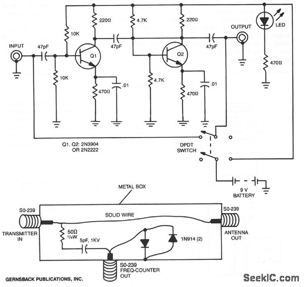
By utilizing a preamplifier with a short length of shielded cable and clip leads, signals that typically do not produce a readout can generate precise and stable readouts on the counter. A DPDT switch is incorporated to bypass the...
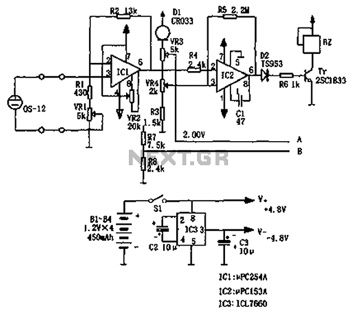
The circuit principle involves an oxygen sensor circuit utilizing the OS-12, a DC amplifier IC1, an A/D converter IC4, a liquid crystal display F2100-34PI, a voltage comparator IC2, and a positive and negative power converter IC, among other components....
Bistable circuit operating at a frequency of 100 kHz or less. A bistable circuit, also known as a flip-flop, is a type of electronic circuit that has two stable states and can be used to store binary information. This circuit...