
200 meters remote control schematic design
The circuit design of early transmitters often relied on LC oscillators, which are known for their susceptibility to frequency drift due to environmental factors such as temperature changes and mechanical vibrations. The introduction of Surface Acoustic Wave (SAW) devices revolutionized this aspect by providing a more stable frequency output. SAW devices utilize the piezoelectric properties of certain materials to generate and manipulate acoustic waves, offering improved frequency stability that rivals traditional crystal oscillators.
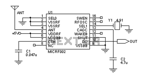
The schematic for the transmitter circuit employing SAW devices typically includes the SAW resonator, which is integrated into the oscillator circuit. This integration simplifies the design, reducing the number of passive components needed compared to conventional crystal oscillator circuits. The stability of the frequency output is crucial, especially in applications where the transmitter may be subject to physical handling or environmental changes.
In the case of the ICRF002 ceramic resonator, its ability to be interchanged with other resonators enables versatility in tuning the reception frequency range from 300 to 440 MHz. This flexibility allows for adjustments based on specific application requirements, such as regulatory compliance or operational range.
The MICRF002 is designed for efficient operation in two distinct modes. In scan mode, the circuit can handle wider bandwidths, making it suitable for applications that require rapid frequency adjustments, such as in frequency-hopping spread spectrum systems. The lower data rate of 2.5 KBytes per second in this mode is a trade-off for the increased bandwidth.
Conversely, the fixed mode provides a more stable operation with a significantly reduced bandwidth, ideal for applications that require reliable data transmission at higher rates of up to 10 KBytes per second. This mode is particularly advantageous for applications where the frequency drift of the transmitter is minimal due to the use of crystal stabilization.
The functionality of the MICRF002 extends beyond mere signal transmission; its wake-up feature is a vital component for low-power applications. This function allows the circuit to remain in a low-power state until activated, thereby conserving energy when the device is not in active use.
Overall, the integration of SAW devices in transmitter circuits, along with the operational flexibility offered by the MICRF002, exemplifies advancements in RF circuit design that enhance performance, stability, and efficiency in modern communication systems.Early transmitters use more LC oscillator frequency drift is more serious. SAW devices appear to solve this problem, the frequency stability of the crystal substantially the sa me, and its fundamental frequency of up to hundreds of megabytes or even gigahertz. Without octave, compared with the crystal oscillator circuit is extremely simple. The following two circuits for the common transmitter circuit, due to the use of SAW devices, the circuit is very stable, even when grasping the antenna, acoustic, or other parts of the circuit, the transmit frequency will not drift. And a compared with Figure II transmission power larger. Up to 200 meters. ICRF002 ceramic resonator and replace it with a different resonators, the reception frequency can cover 300-440MHz.
MICRF002 has two operating modes: scan mode and fixed mode. Scan mode accepts bandwidth of up to several hundred KHz, this mode is mainly used for the LC oscillator and transmitter supporting the use, because, LC transmitter frequency drift is large, in the scan mode, the data communication rate of 2.5KBytes per second. Fixed bandwidth mode only tens of KHz, this mode is used and the use of the crystal frequency stabilization transmitter supporting data rates up to every second 10KBytes.
The operating mode is selected by MICRF002 16 feet (SWEN) implementation. In addition, the wake-up function can wake up decoder or CPU, in order to minimize power consumption. After MICRF002 is complete monolithic superheterodyne receiver circuit, the basic realization of the antenna input data directly, receiving distance is generally 200 meters.
Related Circuits

When fast charging a nickel-cadmium battery, the temperature control circuit, as illustrated in the accompanying figure, is designed to monitor the battery temperature to regulate the charging current. The circuit consists of Icl to IC3, which forms the temperature...

The two neon bulbs will illuminate when the voltage across the ringing circuit exceeds 100 V. These bulbs provide line isolation between the unit and the telephone line. Additionally, they function as a voltage divider for the bridge rectifier...
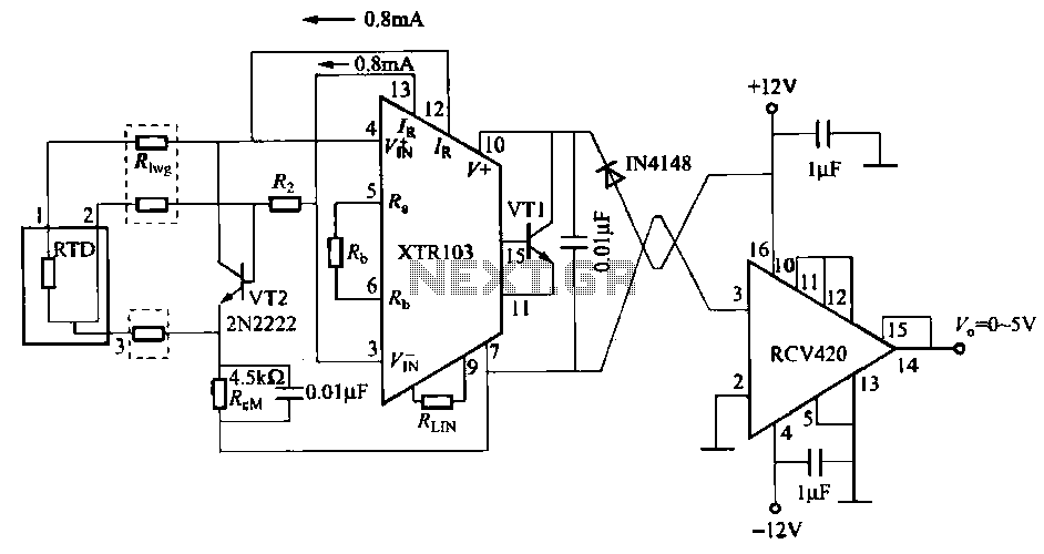
When the RTD temperature sensor is positioned far from the amplifier, the resistance of the sensor leads and their susceptibility to interference and other issues cannot be overlooked. The circuit shown in the figure addresses this problem. It utilizes...
LBl690 is a three-phase brushless DC motor drive control integrated circuit manufactured by Sanyo, a Japanese company. It is extensively utilized in both domestic and imported applications for broken wind and fresh air conditioning systems that require brushless DC drive...
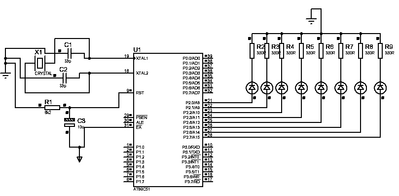
The first "Hello World!" project preferred for microcontrollers is LED blinking. An ATMEL 89C51 (40-pins DIP) microcontroller, based on the 8051 architecture, is used, which is ideal for first-time learning of MCU chips. The program is very simple and...
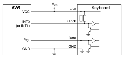
In many situations, a human interface is required for microcontroller projects. This example describes the interfacing of an AVR microcontroller with a standard PC AT keyboard. According to the keyboard timing diagram, the keyboard transfers data to the host...
Warning: include(partials/cookie-banner.php): Failed to open stream: Permission denied in /var/www/html/nextgr/view-circuit.php on line 713
Warning: include(): Failed opening 'partials/cookie-banner.php' for inclusion (include_path='.:/usr/share/php') in /var/www/html/nextgr/view-circuit.php on line 713