
Nickel-cadmium battery fast charger temperature control circuit
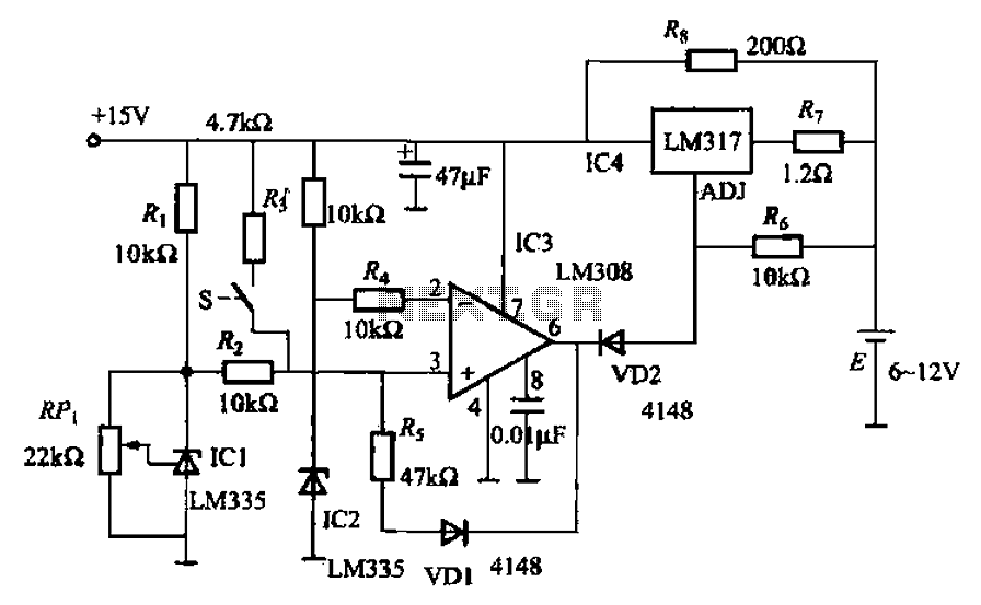
The described circuit effectively manages the charging process of a nickel-cadmium battery by incorporating a temperature control mechanism that ensures safe and efficient operation. The use of integrated circuits (ICs) allows for precise monitoring and regulation of the charging current based on the battery's temperature. The temperature control circuit is crucial for preventing overheating during fast charging, which can lead to battery damage or reduced lifespan.
The configuration of the circuit includes several key components: Icl, IC2, IC3, and IC4. The temperature sensors IC1 and IC2 are strategically placed to provide accurate readings of the battery temperature. The output from these sensors is compared within IC3, which acts as a comparator to determine if the battery temperature exceeds the predefined threshold. If the temperature is too high, the output from IC3 drops, triggering VD2 to conduct and modifying the charging current supplied by IC4 to a lower, safer level.
The constant current mode, maintained at approximately 1A, ensures that the battery is charged efficiently without risking thermal runaway. The transition to trickle charge mode, initiated by the output of IC4, allows the system to maintain the battery's charge while preventing overheating. This dual-mode charging strategy enhances the reliability of the charging process, prolonging the battery's life and ensuring optimal performance.
In summary, the circuit described provides a robust solution for fast charging nickel-cadmium batteries, integrating temperature monitoring and adaptive charging strategies to enhance safety and efficiency. The careful selection of components and their arrangement within the circuit ensures that the charging process remains within safe operational limits, safeguarding both the battery and the charger. Cause when fast charging nickel-cadmium battery temperature, as shown in FIG nickel-cadmium battery fast charger temperature of the control circuit can be provided to detect th e temperature of the battery, so as to control the charging current. Icl ~ lC3 constituting the temperature control circuit, 1C4 charging circuit. IC1, IC2 temperature testing, adjusting section RPi, the ratio of the output voltage IC1 IC2 output voltage slightly higher than 50mV. Thus, before the thermostat does not start, feet potential voltage comparator IC3 than feet high, output is high, VD2 deadline, IC4 constant current of about 1A of the battery.
IC2 affixed to the surface of the battery to be charged, when the battery temperature rises to a certain temperature, which is higher than the potential of feet feet potential, IC3 output low, VD2 conduction through, IC4 the ADJ pin is about 0.7V low potential output is constant pressure to maintain the trickle charge mode, the battery temperature decreases. Similarly, when the temperature falls to the previous temperature, but also restored constant current charging.
Related Circuits
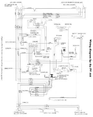
The following circuit illustrates the wiring diagram for the Volvo PV444, a vintage car electrical circuit. It provides an electrical understanding of this uni-body vehicle. The Volvo PV444 wiring diagram serves as a crucial reference for understanding the electrical system...
The ptPC1891A application circuit features a working state switch (SA) with a total of four options. It primarily utilizes ICs 11 and 12 to set different logical levels, as referenced in Table 5-12. The high level is denoted as...
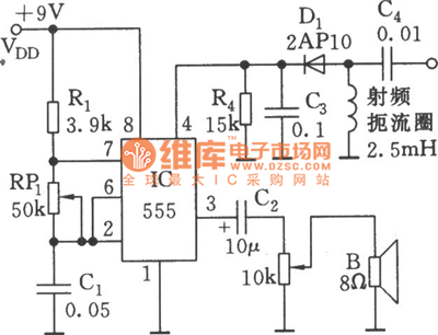
As shown in the figure, the 555 timer, resistors R1, RP1, and capacitor C1 form a controlled audio oscillator. The frequency of the oscillator is given by the formula f = 1.44 / ((R1 + 2 * RP1) *...
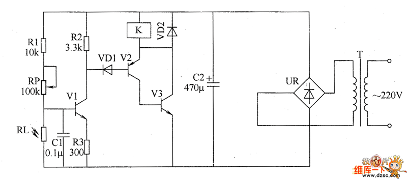
The optical safety switch circuit includes a power supply circuit, a light control circuit, and a control implementation circuit (switch circuit). The power circuit is made up of a power transformer (T), a bridge rectifier (UR), and a filter...
This article presents a high reliability 1200V High Voltage Integrated Circuit (1200V HVIC) for half bridge driver applications, aimed at reducing the IC's supply current by approximately 50%. The 1200V High Voltage Integrated Circuit (HVIC) is designed specifically for half-bridge...
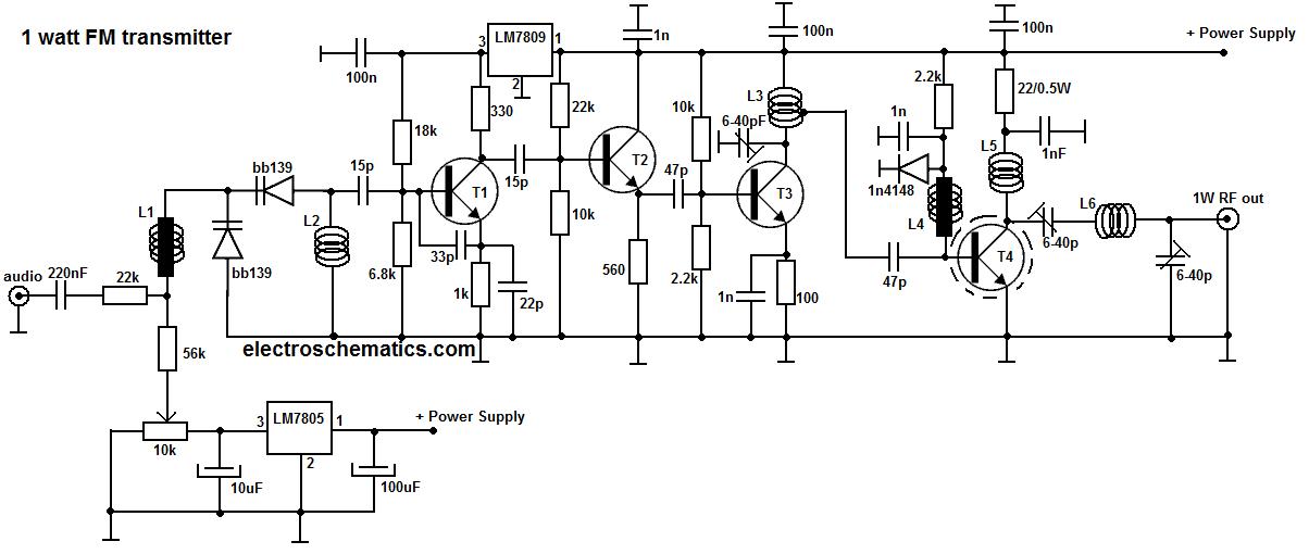
This portable FM transmitter features a limiter, a microphone amplifier, and PLL digital tuning, all integrated onto a single circuit board. The RF power output can be switched between 1 W (high) and 0.2 W (low). The schematic is...