
2000 Chevrolet Chevy Blazer Wiring Diagram
The wiring diagram for the 2000 Chevrolet Chevy Blazer serves as an essential reference for understanding the electrical system and its various components. The power distribution schematic illustrates how electrical power is routed throughout the vehicle, ensuring that all systems receive the necessary voltage for operation.
The fuel pump relay control is a critical element, responsible for managing the power supply to the fuel pump. This relay is activated by the vehicle control module, which monitors various engine parameters to determine when fuel is needed. The fuel pump and sender work in conjunction to supply fuel to the engine while providing feedback on fuel levels to the vehicle's dashboard gauge.
The splice pack is an important feature, as it consolidates multiple wire connections into a single point, simplifying the wiring layout and enhancing the reliability of electrical connections. The fuel pump prime connector allows for manual activation of the fuel pump, useful for troubleshooting or priming the fuel system after maintenance.
The ground distribution schematic ensures that all electrical components have a common return path to the battery, reducing the risk of electrical noise and ensuring stable operation. The underhood fuse block houses various fuses that protect the electrical circuits from overloads, while the vehicle control module serves as the brain of the vehicle's electrical system, coordinating the operation of multiple systems for optimal performance.
In summary, the wiring diagram encapsulates the interconnections and functionalities of the electrical components within the 2000 Chevrolet Chevy Blazer, providing a comprehensive overview for diagnostics and repairs.The Part of 2000 Chevrolet Chevy Blazer Wiring Diagram: power distribution schematic, fuel pump relay control, fuel pump and sender, splice pack, fuel pump prime connector, ground distribution svhematic, underhood fuse block, vehicle control module, fuel pump relay control. 🔗 External reference
Related Circuits
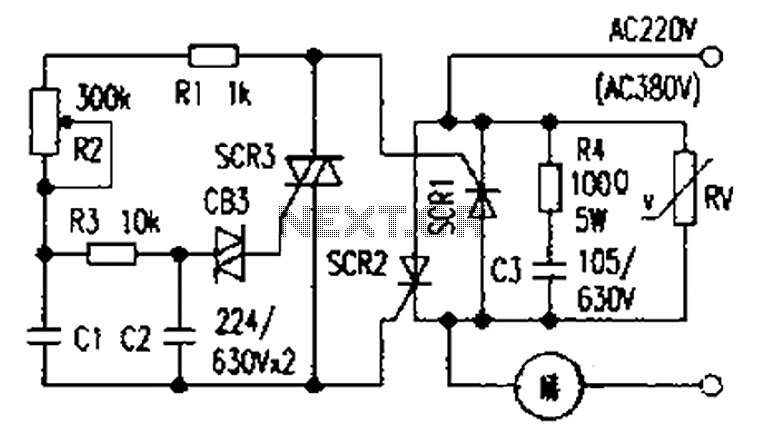
The presentation of a general power thyristor trigger circuit is more complex, and some components are difficult to procure. A successful trigger circuit has been constructed for only a few dollars. This circuit is designed to trigger a thyristor...
The tank circuit consisting of capacitor C2 and inductor L1 is utilized to tune the transmitter. The antenna is coupled to the transmitter through capacitor C3 and can be either a telescopic antenna or a length of hookup wire....
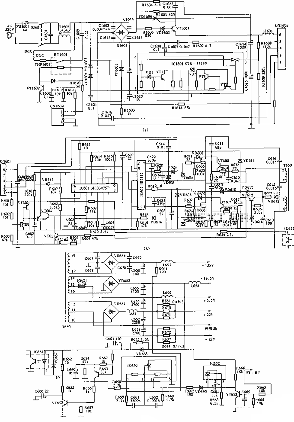
The circuit of the Sony KV-S29MHl (S Movement series) TV switching power supply (SIR a 80145A) consists of three main sections: (A) the power oscillation part, (B) the regulator part, and (C) the output section. The Sony KV-S29MHl TV switching...
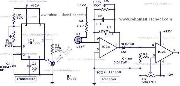
All components used in the Moving Sensor/Detector Schematic Diagram utilize the IC NE555 and the Phototransistor L14F. The primary component in this circuit is the IC NE555, along with an IR LED, the Phototransistor L14F, and the IC LM1458....
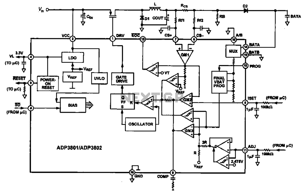
Charging circuit diagram for personal work based on the operating principle of ADP3801/3802 charging circuit. The ADP3801/3802 is a highly integrated battery charger controller designed for Li-ion and Li-polymer batteries. The charging circuit typically consists of several key components including...
The TDA8444 is a digital-to-analog (D/A) converter integrated circuit (IC) produced by Philips. It is designed to convert digital signals into analog signals. The TDA8444 IC utilizes a 16-pin dual in-line package, with specific pin functions and data outlined...
Warning: include(partials/cookie-banner.php): Failed to open stream: Permission denied in /var/www/html/nextgr/view-circuit.php on line 713
Warning: include(): Failed opening 'partials/cookie-banner.php' for inclusion (include_path='.:/usr/share/php') in /var/www/html/nextgr/view-circuit.php on line 713