
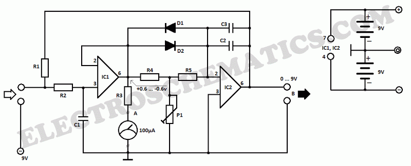
200mA per Hour 12V NiCAD Battery Charger circuit
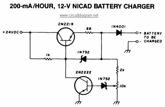
The 12V NiCAD battery charger circuit is designed to provide a reliable and efficient charging solution for NiCAD batteries. The circuit operates by initially supplying a charging current of 75mA, which is optimal for the safe and effective charging of NiCAD cells. The transition to a trickle charge once the battery is fully charged is critical for maintaining battery health, as it prevents overcharging and reduces the risk of damage to the cells.
The inclusion of current and voltage limiting features is paramount in ensuring the longevity of the battery. These mechanisms help to prevent excessive current flow that can lead to overheating and electrolyte loss. The feedback control system continuously monitors the battery's state of charge, allowing for real-time adjustments to the charging parameters.
Indicator components, such as the lamp (L1) and LED, serve as visual cues to the user regarding the charging status of the battery. The bright illumination of the lamp during charging indicates that the battery is in the process of being charged, while the LED's behavior provides additional feedback on the battery's charge state.
For applications involving lead-acid batteries, the circuit provides an initial charging voltage of 2.5V per cell, which is essential for rapid charging. The gradual decrease in charging current as the battery approaches full charge ensures that the cells are not subjected to stress, further enhancing their lifespan.
The adjustable nature of this charger allows it to accommodate various configurations of NiCAD batteries, whether they are arranged in series or parallel. The maximum voltage rating of 18V ensures compatibility with standard battery configurations while preventing damage due to overvoltage.
Power transistors Q1 and Q2, used as series regulators, play a crucial role in maintaining stable output voltage and current levels, ensuring that the batteries are charged efficiently without exceeding safe operational limits. The design is versatile and can be adapted for solar-powered applications, emphasizing the importance of proper voltage management when integrating with solar panels. Overall, this circuit represents a comprehensive solution for charging NiCAD batteries while prioritizing safety and efficiency.200mA per Hour 12V NiCAD Battery Charger circuit. This NiCAD battery charger circuit charges the battery at 75 mA until the battery is charged, then it reduces the current to a trickle rate. The following diagram is the schematic diagram of 12V NiCAD battery charger with charging rate of 200mA/Hour.
This NiCAD battery charger circuit charges t he battery at 75 mA until the battery is charged, then it reduces the current to a trickle rate. It will fully recharge a dead/unpowered battery in 4 hours and the battery. The following diagram is the schematic diagram of Ni-CAD Battery Charger circuit which featured with current and voltage limiting to keep the battery lifetime. The lamp L1 will be light brightly and the LED will be out when the battery is low and battery charging in progress, but the LED is very bright and the.
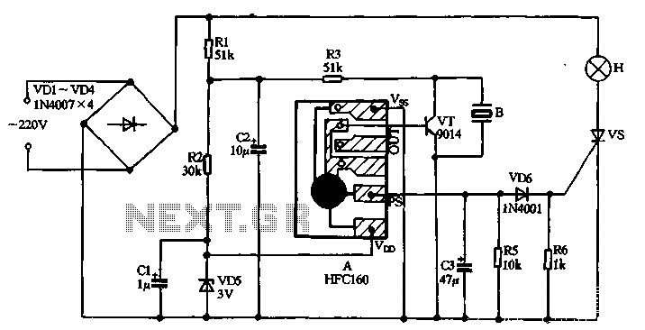
Here is a simple and easy to build circuit diagram of a 12V car battery charger: The above circuit claimed have ability to prevent battery overcharge that make electrolyte lost due to evaporation. This circuit will eliminate the problems by monitoring the battery`s condition of charge through its retroactive control circuit by applying a high.
The following diagram is the circuit diagram of Lead-Acid battery charger. This circuit provides an initial voltage of 2. 5 V per cell at 25 ƒ to quickly charge the battery. The charging current decreases as the battery is charging, and when the current drops to 180 mA, the charging circuit reduces the output voltage of. This battery charger circuit is regulated and adjustable to make this circuit able to charge the mosto NiCAD battery.
This circuit will work for single cell or multi battery cell which connected with series/parallel connection. The maximum voltage of the batteries should be 18V maximum. Power transistors Q1 and Q2 are connected as series regulators. This is the schematic diagram of solar powered mobile phone battery charger. The circuit is designed to charge the battery from a source with a lower voltage. Do not use it to charge the battery with the same or lower voltage than the voltage which is generated by the solar panel.
For proper operation of. 🔗 External reference
Related Circuits
220V AC power is supplied through a VD1 to VD4 bridge rectifier and a voltage regulator circuit involving R1, R2, and VD5 components. The output provides a DC voltage of approximately 3V, which powers the manifold A. The manifold...
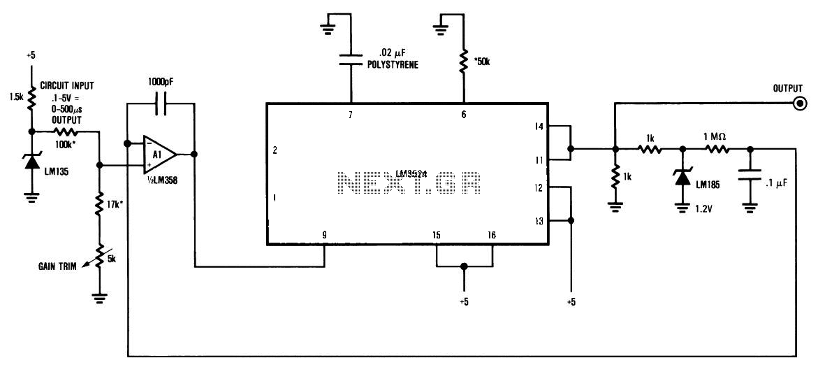
The circuit is a temperature-to-pulse-width converter. The LM3524 is used to convert the output of an LM135 temperature transducer into a pulse width that can be measured by a digital system, such as a microprocessor-controlled data acquisition system. In...
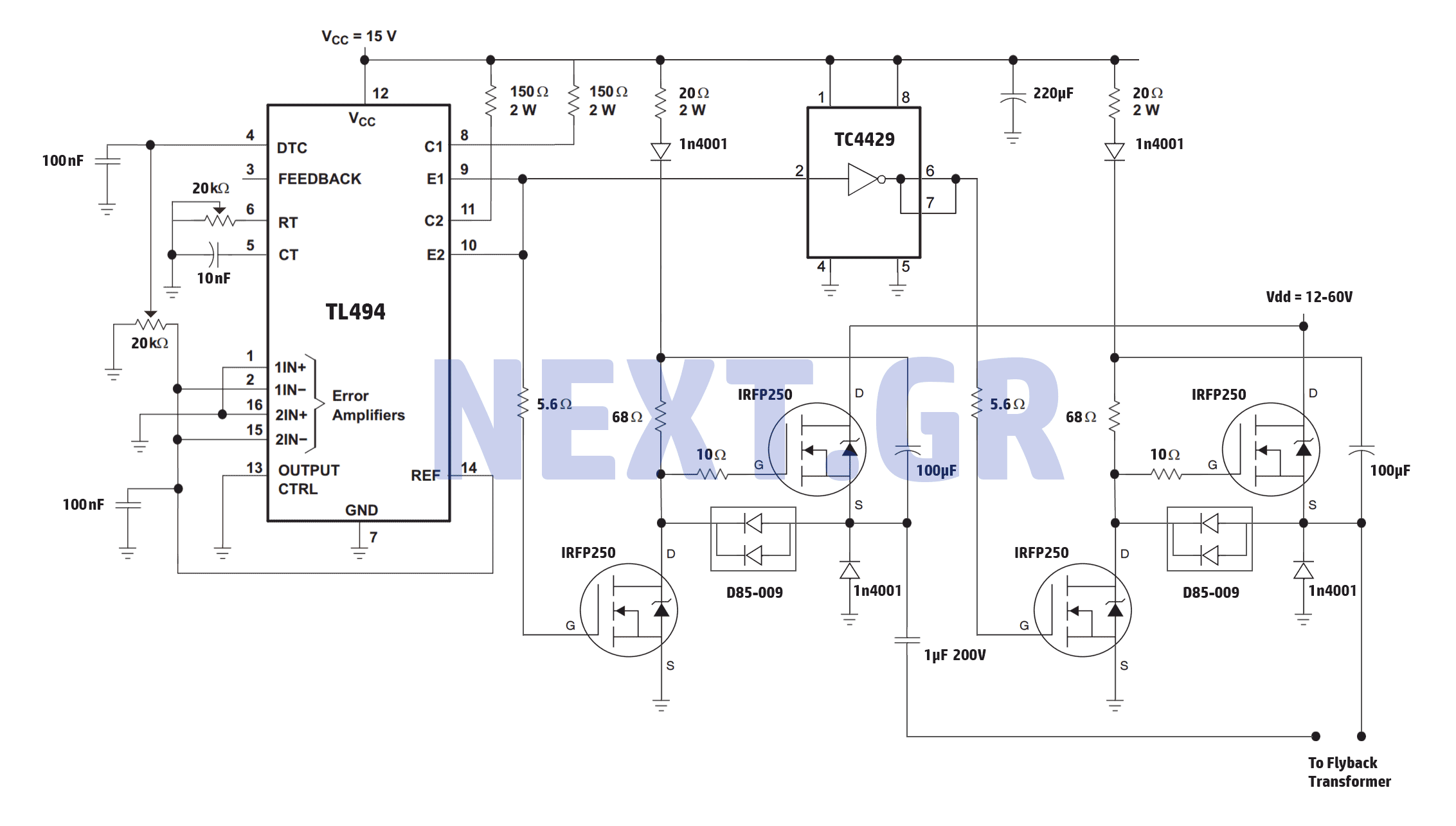
A reliable full bridge driver is essential for driving a flyback transformer. While many flyback driver schematics exist, most lack durability. The well-known Zero Voltage Switching (ZVS) driver, invented by Vladmiro Mazilli, is recognized for its reliability due to...
This lie detector circuit diagram provides two readings: one for challenging questions directed at the subject and another to display the subject's emotional state in general. The emotional states are detected not only by heart rate variations and perspiration...
This is the schematic diagram of a 15W inverter circuit. The circuit is based on a PNP power transistor such as the TIP32 and other similar transistors. This inverter produces a square wave output, which may cause some noticeable...
JBD3-10 leakage protection circuit The JBD3-10 leakage protection circuit is designed to detect and mitigate leakage currents in electrical systems, enhancing safety and preventing potential hazards. This circuit employs a differential current transformer that continuously monitors the current flowing through...