
200W Valve RF Transmitter circuit
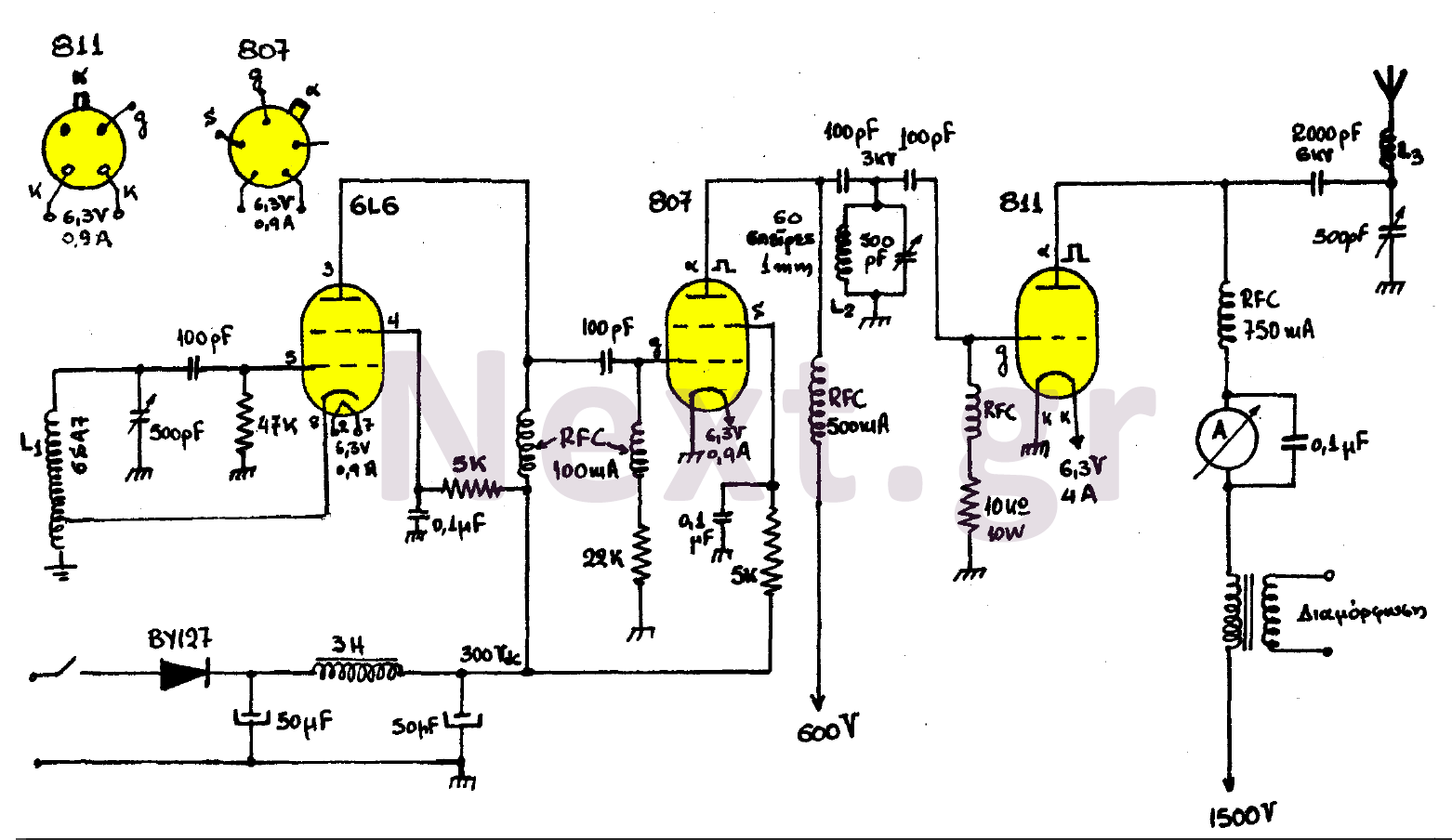
The transmitter must be constructed with minimal wiring and requires tuning. Tuning is accomplished using variable capacitors along with a milliammeter connected to the 807 tube's plate. The milliammeters on the plate of each tube should be adjusted to indicate the minimum reading, while the milliammeters of any other tube should reflect the maximum reading. The configuration of the transmitter is established from the final stage, particularly its plate, through a modulation transformer that is part of the final section of an audio amplifier. The modulator's power for proper configuration must be 30W.
The transmitter design is structured to optimize performance while maintaining simplicity in wiring. The oscillator stage, which employs a 6L6 tube, generates the initial radio frequency signal. The use of a 6SA7 coil provides the necessary inductance to ensure stable oscillation. The oscillator's output is then fed into the amplifier isolator stage featuring an 807 tube, which serves to amplify the signal while isolating it from the feeding device using radio frequency chokes (RFCs). These RFCs are crucial for preventing feedback and ensuring that the generated RF does not interfere with the input circuitry.
In the final stage, the 811 tube amplifies the signal to the desired power level. The tuning process is critical for achieving optimal performance, as it ensures that the transmitter operates efficiently at the intended frequency. The variable capacitors allow for fine adjustments, while the milliammeters provide feedback on the operating conditions of each tube, ensuring that they are functioning within their optimal ranges.
The modulation transformer plays a vital role in the final stage, allowing for the modulation of the RF signal with audio frequencies, thus enabling the transmission of voice or other audio signals. The requirement for a 30W modulator power indicates that the transmitter is designed for robust performance, suitable for applications where reliable signal transmission is essential. Proper assembly and tuning of this transmitter will result in a highly efficient and effective communication device.This transmitter consists of three stages. The step of the oscillator with the 6L6 lamp, the amplifier isolator with the lamp 807 and the final stage of the transmitter with the 811 lamp. The coil L1 is requested by the market as a coil of the 6SA7. The various RFCs are sold on the market and used to isolate the feed device from the generated radio frequencies.
After the transmitter has to be made with the smallest possible wiring, the transmitter must be tuned. The tuning is done with the variable capacitors and with a milliamometer connected to the 807 rise. The milliamerometers on the rise of each lamp should be Tuning to indicate the minimum indication while the milliamerometers of any lamp have the maximum indication.
The transmitter configuration is made from the final stage and in particular from its rise by means of a modulation transformer that is part of the final step of an acoustic amplifier.
The power of the modulator for correct configuration must be 30W.
Related Circuits
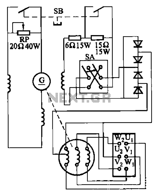
The AX3-300-2 DC arc welding machine circuit is part of the AX, AX1, AX3, and AR series of rotary DC arc welding machines. These machines share a similar structural design, featuring a three-integral unit configuration that combines an inverter...

This is a design circuit for a UHF transmitter. The TV transmitter operates within the UHF frequency range of 470-580 MHz, specifically on channels 21-34. It can transmit signals over distances of 30-100 meters using a cable length of...
This index is organized alphabetically by each word (excluding prepositions). For instance, the "Frost Alarm" will be listed under both "A" and "F". To efficiently locate a circuit, utilize the top index or employ your browser's search feature. In...

This is a simple and inexpensive FM transmitter. The circuit operates at a low voltage using a CR2025 3V battery with low current consumption. The total size of this FM transmitter, including the battery but excluding the antenna, is...
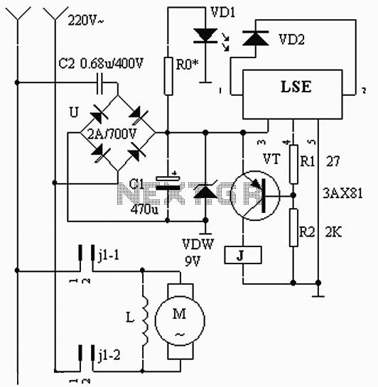
The circuit operates based on the interaction between an infrared light-emitting diode (VD1) and an infrared receiver diode (VD2). When VD1 emits infrared radiation, it is detected by VD2, which causes a decrease in its internal resistance. This change...

A CMOS clock circuit is capable of driving a multi-digit gas discharge display. This simple circuit does not include an alarm feature but allows for a flashing colon to indicate morning and afternoon. The circuit requires seven drive circuits...