
uhf tv transmitter circuit

The UHF transmitter circuit is designed to operate effectively within the specified frequency range, making it suitable for various applications in television broadcasting. The circuit typically consists of several key components, including an oscillator, modulator, amplifier, and antenna.
The oscillator generates the carrier frequency, which is essential for transmitting the signal. It is crucial that the oscillator is precisely tuned to the desired frequency (within the 470-580 MHz range) to ensure optimal performance. The modulator is responsible for encoding the audio and video signals onto the carrier wave, enabling the transmission of television content.
An amplifier is integrated into the circuit to boost the power of the modulated signal before it is transmitted. This amplification is vital for achieving the desired transmission range of 30-100 meters. The choice of components for the amplifier, such as transistors or integrated circuits, will significantly impact the overall efficiency and effectiveness of the transmitter.
The antenna plays a critical role in radiating the transmitted signal into the surrounding environment. The design of the antenna should be matched to the operating frequency to maximize radiation efficiency. A cable length of 10-20 cm is typically used to connect the antenna to the transmitter circuit, which helps in maintaining the proper impedance and minimizing signal loss.
Power supply considerations are also essential for the reliable operation of the UHF transmitter. A voltage range of 9-15 volts is recommended, with the option to use 9V DC batteries for portability. It is important to ensure that the power supply can deliver sufficient current to all components, particularly during peak transmission periods.
Finally, the construction of the coil is a critical element in the design of the UHF transmitter. The coil's dimensions, including the number of turns and the diameter, must be calculated to resonate at the desired frequency. This resonant frequency is determined by the inductance of the coil and the capacitance in the circuit. Proper tuning and adjustments may be necessary to achieve the best performance from the transmitter.
In summary, the UHF transmitter circuit is a sophisticated design that requires careful attention to component selection, tuning, and construction techniques to ensure effective television signal transmission within the specified frequency range.This is design circuit for UHF transmitter circuit. The TV transmitter circuit is working on the UHF channel, 470-580 MHz frequency channel 21-34. This transmitter can radiate as far as 30-100 meters by using a cable 10-20 cm. This is the figure of the circuit. TV transmitter requires supplies voltage of 9-15 Volt. However, you can also use 9v VDC or batteries. This is an important thing to remember for building of the TV transmitter circuit is that the dimensions of coil size to match the frequency of the desired work. The value of the spindle is making coil as follows: 🔗 External reference
Related Circuits
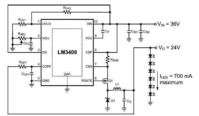
This dimming-controlled LED driver electronic circuit requires an input voltage of 36 volts and will provide an output voltage of 24 volts at a maximum current of 700 mA. The described dimming-controlled LED driver circuit is designed to efficiently convert...
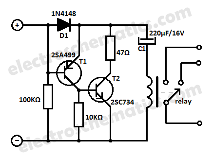
This low current relay circuit is designed for use in battery-operated electronic devices. Its operating current is in microamperes (µA). This is achieved by using a bistable relay and incorporating additional components to enable the relay to function like...
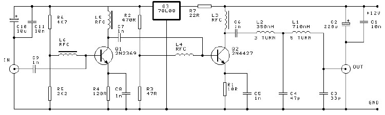
A high-efficiency, simple two-transistor VHF amplifier electronic circuit project can be developed using the provided circuit diagram. This VHF amplifier circuit achieves a significant efficiency with a gain of approximately 16 dB and does not require any tuning or...
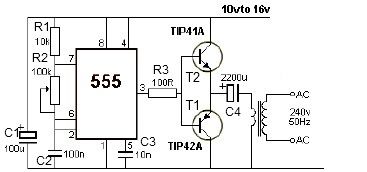
12V power inverter circuit utilizing a 555 timer for an electronic project. The 12V power inverter circuit is designed to convert a DC voltage of 12 volts into an AC voltage suitable for powering small electronic devices. The core component...
This set of two circuits forms the basis for a simple light wave transmitter. A laser beam is modulated and directed towards a receiver that demodulates the signal and presents the information, such as voice or data. The assembly...
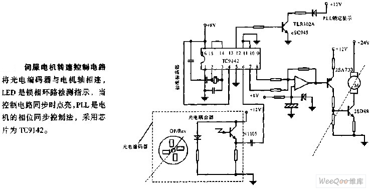
The servo motor speed control circuit connects the photoelectric encoder to the motor shaft. The LED serves as an indicator light for the phase-locked loop (PLL) detection, illuminating when the control circuit is synchronized. The PLL employs a phase...