
20Hz audio bandpass filter
The audio line-out or headphone output from a VHF/UHF scanning or communications receiver is connected to the input of the bandpass filter. The output of the bandpass filter is connected to a digital frequency meter (DFM), and/or audio monitor speaker. A monitor speaker is used when tweaking the filter's resonant frequency. If a DFM is not used, a PC program, such as Spectrum Lab could be used for spectral display of TV video carriers on a computer screen. The tuning range of the filter is from approximately 400 Hz to 4 kHz, when using a 50 kΩ potentiometer. The typical tuning is around 1000-1300 Hz, corresponding to the maximum output level of 2.4 kHz in USB mode. A 10 kΩ fine tuning potentiometer has also been added (not shown on the schematic). This can be included in series with the main 50 kΩ pot. The fine-tuning adjustment allows for a more precise setting, improving the bandspread by a factor of about four times up to 2 kHz. This feature is particularly useful for receivers with 100 Hz minimum tuning steps, such as the Icom R7000/7100/8500 series. Initially, an LM348 operational amplifier was used in the circuit. However, replacing the LM348 with an LM6134BIN integrated circuit resulted in improved high-frequency response. It is important to note that only one single IC is used in the bandpass circuit; the four op-amps indicated on the circuit diagram are all contained within this one IC. Additionally, a bypass switch has been incorporated to enable audio frequencies above the filter's resonant frequency.
The schematic for this audio bandpass filter includes a series configuration of the low-pass and high-pass filters, with the input connected to the audio source and the output directed to either the DFM or audio monitor. The tuning components consist of the primary 50 kΩ potentiometer and the optional 10 kΩ fine-tuning potentiometer, which can be adjusted to achieve the desired frequency response. The LM6134BIN op-amp provides the necessary amplification and filtering capabilities, ensuring that only the selected frequency range is passed through while minimizing unwanted signals. The bypass switch enhances versatility by allowing signals outside the tuned range to be processed as needed. This design effectively addresses the challenges of weak signal amplification and filtering in various communication applications, making it a valuable tool for audio and video carrier separation.This audio bandpass filter is useful for amplification and filtering of weak AM TV video carriers. For example, a DFM (digital frequency audio multimeter) may have insufficient input sensitivity for measuring extremely weak SSB TV video audio signals. By using the 20 Hz filter to peak the wanted carrier, the DFM will display the carrier frequency. Another possible application for this filter is increased amplification and reduced bandwidth of weak BCB heterodyne AM carriers.
The filter is also very useful for separating video carriers that are in close proximity of each other. By definition, a bandpass filter is usually a low-pass and high-pass filter in series, allowing only a certain range of frequencies through.
Because the cut-off frequencies are close to one another, the effect will be similar to that of a peaking filter.
The audio line-out or headphone output from a VHF/UHF scanning or communications receiver is connected to the input of the bandpass filter. The output of the bandpass filter is connected to a digital frequency meter (DFM), and/or audio monitor speaker.
A monitor speaker is used when tweaking the filter's resonant frequency. If a DFM is not used, a PC program, such as Spectrum Lab could be used for spectral display of TV video carriers on a computer screen. The tuning range of the filter is from ~ 400 Hz to 4 KHz, when using a 50 KHz potentiometer. The writer typically tunes the filter to resonate around ~ 1000-1300 Hz. This frequency range corresponds to the maximum output level of 2.4 KHz USB mode. A 10K fine tuning potentiometer has also been added (not shown on the schematic). This can be included in series with the main 50K pot. I did this on my filter, and the centre of the tuning range moved from 300 Hz to 1000 Hz and improved the bandspread by a factor of about 4 times up to 2 kHz.
A fine tune pot is useful for use with receivers that have 100 Hz minimum tuning steps, for example, Icom R7000/7100/8500, etc. Initially, a LM348 op-amp was used in the circut. Although this worked ok, it was found that by replacing the LM348 with a LM6134BIN IC, improved high frequency response was obtained.
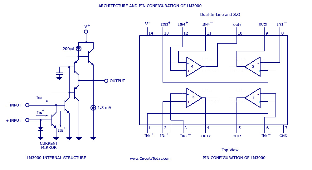
Please note that only one single IC is used in the band pass circuit. The four op-amps indicated on the circuit diagaram are all contained within one IC. The author has also fitted a by-pass switch, to enable audio frequencies above the filters resonant frequency.
Related Circuits
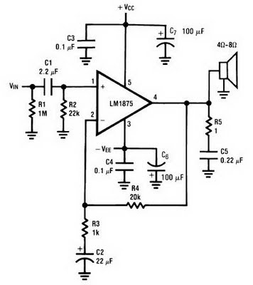
The amplifier circuit can be constructed using the LM1875 power amplifier IC. The LM1875 is a single-chip power amplifier from National Semiconductor. This 20-watt audio amplifier is characterized by low power consumption while delivering high-quality sound suitable for use...
One of the limitations affecting all real amplifiers is the finite signal bandwidth. This implies that any amplifier constructed or utilized has an upper limit to the range of sinewave frequencies it can amplify. Consequently, high-frequency signals may not...
The acoustic filters are met in various points in the sound systems. The knownest application they are the filters baxandal for regulating tone low and high frequencies and filters crossover where the acoustic region is separated in subareas, in...
A simple multi-channel audio mixer circuit utilizing the LM3900 quad amplifier is presented below. The circuit features a four-channel quad amplifier (LM3900) with two microphone audio inputs and two direct line inputs. By paralleling additional circuits, the number of...
A window comparator formed by two operational amplifiers packaged into IC1 is the heart of the circuit below. With this technique, we can detect precisely and symmetrically. The window comparator circuit utilizes two operational amplifiers (op-amps) configured to create a...
Utilizing an analog audio line delay, it is possible to virtually adjust the size of a room. By simply turning a knob on the audio equipment, one can modify the perceived room size. The circuit described herein facilitates this...