
Audio Signal Clipping Indicator
The window comparator circuit utilizes two operational amplifiers (op-amps) configured to create a defined voltage range, or "window," within which an input signal must fall for the output to indicate a specific state. The circuit employs IC1, which houses the two op-amps, to achieve this functionality efficiently.
The first op-amp is configured as a non-inverting comparator, with its non-inverting input connected to a reference voltage, typically set by a voltage divider. The inverting input is connected to the input signal. When the input signal exceeds the reference voltage, the output of this op-amp transitions to a high state, indicating that the input has crossed the upper threshold of the window.
Conversely, the second op-amp is configured as an inverting comparator. Its inverting input is connected to a lower reference voltage, also established by a voltage divider, while the non-inverting input receives the input signal. When the input signal drops below this lower reference voltage, the output of the second op-amp switches to a high state, indicating that the input has fallen below the lower threshold of the window.
The outputs of both op-amps can be connected to a logic gate or a microcontroller to provide a clear indication of whether the input signal is within the defined window. This configuration allows for precise detection of signals that fall within a specific range, making it suitable for applications in signal conditioning, level detection, and various control systems. The symmetrical design ensures that both upper and lower thresholds are equally significant, providing a balanced response to the input signal variations.A window comparator formed by two op-amps packaged into IC1 is the heart of the circuit below. With this technique, we can detect precisely and symmetrically.. 🔗 External reference
Related Circuits
It is advisable to modify inexpensive USB speakers to obtain a pre-assembled analog front-end for this project. If this is not feasible, then soldering will be necessary, requiring a minimum of two resistors and one capacitor, assuming the display...
Can be directly connected to CD players, tuners and tape recorders. Simply add a 10K Log potentiometer (dual gang for stereo) and a switch to cope with the various sources you need. A correct grounding is very important to...
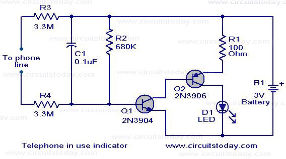
The circuit shown here serves as an indicator for when a telephone receiver is off-hook. It can be integrated with older telephone models that lack this feature. The circuit employs a complementary Darlington pair consisting of Q1 (2N3904) and...
This compact circuit transmitter processes audio signals from a table or microphone, as well as video signals from a camera, DVD, or video cassette. It can transmit these signals directly from a computer over a free VHF channel. The...
Audiostrobe glasses are utilized alongside light and sound machines, as well as certain brainwave entrainment software. The glasses are equipped with built-in LEDs. Audiostrobe glasses are designed to enhance the sensory experience provided by light and sound machines, which are...
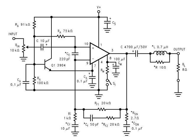
The LM2876 audio power amplifier circuit can be designed as a simple, high-efficiency power audio amplifier capable of delivering 40W of continuous average power to an 8-ohm load with a total harmonic distortion plus noise (THD+N) of 0.1% from...
Warning: include(partials/cookie-banner.php): Failed to open stream: Permission denied in /var/www/html/nextgr/view-circuit.php on line 713
Warning: include(): Failed opening 'partials/cookie-banner.php' for inclusion (include_path='.:/usr/share/php') in /var/www/html/nextgr/view-circuit.php on line 713