
20W Power Tube Amplifier with EL34
The 20W power amplifier circuit utilizing the EL34 tube is designed to deliver high-quality audio amplification with a warm, rich sound characteristic of tube amplifiers. The EL34 tube operates in a push-pull configuration, which enhances efficiency and reduces distortion, making it suitable for various audio applications.
The circuit typically includes several key components: a power supply section, input and output stages, and biasing resistors. The power supply section is responsible for providing the necessary high voltage to the EL34 tubes, typically around 400V, along with a lower voltage for the tube filaments. The input stage often consists of a preamplifier circuit that may include additional tubes or solid-state devices to prepare the audio signal for amplification.
In the output stage, the EL34 tubes amplify the audio signal, which is then passed through output transformers. These transformers are essential for matching the high impedance of the tubes to the lower impedance of speakers, ensuring efficient power transfer and optimal sound quality.
Biasing resistors are crucial for setting the operating point of the tubes, which affects the linearity and overall performance of the amplifier. Proper biasing ensures that the tubes operate within their optimal range, minimizing distortion and maximizing output power.
Overall, the circuit diagram of the 20W power amplifier using the EL34 tube represents a classic design that combines simplicity with effective audio performance, making it a popular choice among audiophiles and audio engineers.The following diagram is the circuit diagram of 20W power amplifier which build based tube component EL34. EL34 is very famous tube and great for power tube amplifier. The circuit above is complete circuit contains tube amplifier circuit di.. 🔗 External reference
Related Circuits
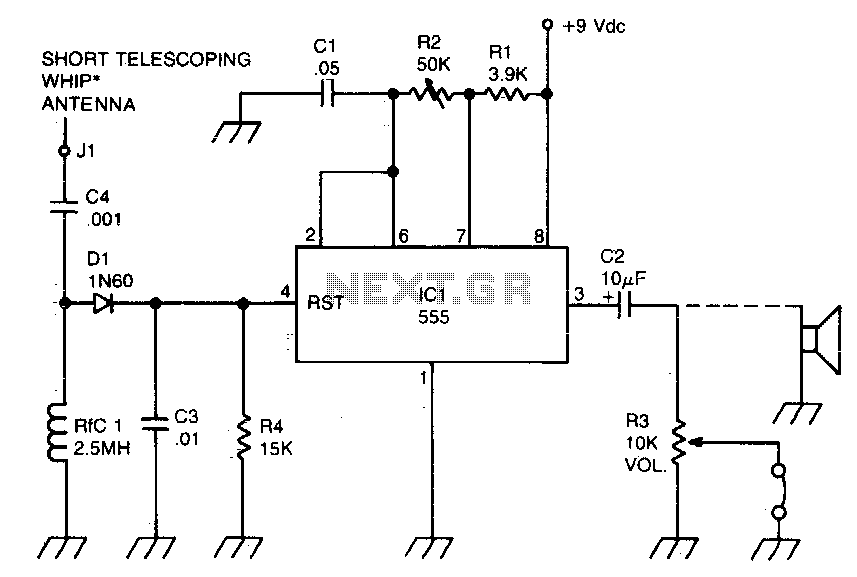
A sidetone oscillator is a specific type of audio astable multivibrator. Keying is achieved by turning the oscillator on and off through the application of a positive DC potential, which is generated from the RF signal to the reset...
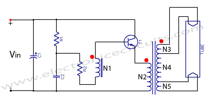
Fluorescent tube light circuit of an inverter that uses a single transistor and a single transformer. This type of inverter can be made in various configurations. The fluorescent tube light circuit described utilizes a basic inverter design that incorporates a...

Below is a proof of concept circuit which needs improvement. The part values shown will run a high efficiency red LED with a Vf of 1.9V from only 2 nicads, right down to 2 volts. For a white LED...
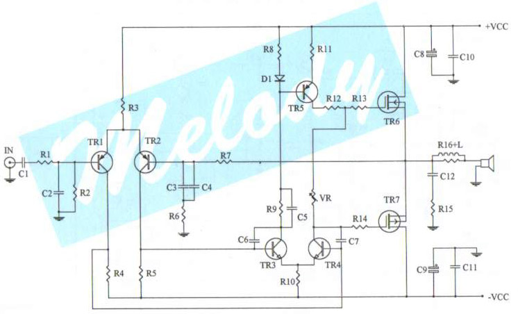
The schematic diagram of a 100-watt audio amplifier utilizing MOSFET technology. A comprehensive collection of electronic circuit diagrams is available, including a 100W RMS amplifier and a 0-30V stabilized variable power supply with current control. The 100-watt audio amplifier schematic...
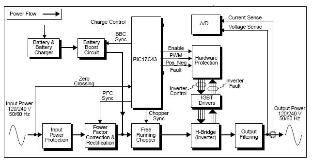
The UPS (Uninterruptible Power Supply) Reference Design offers a pre-designed uninterruptible power supply solution utilizing the flexibility of the PIC17C43 microcontroller. This microcontroller is noted for its low-cost and high-performance capabilities, which are not typically found in other microcontrollers....
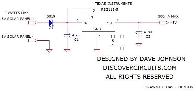
The simple circuit below regulates the voltage from a 6V solar panel to a fixed +5V. This voltage can be supplied to any cell phone or USB-connected portable device to charge its battery. The circuit utilizes a Reg113-5 voltage...
Warning: include(partials/cookie-banner.php): Failed to open stream: Permission denied in /var/www/html/nextgr/view-circuit.php on line 713
Warning: include(): Failed opening 'partials/cookie-banner.php' for inclusion (include_path='.:/usr/share/php') in /var/www/html/nextgr/view-circuit.php on line 713