
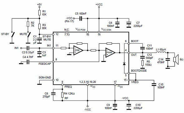
TDA1521 / TDA1521Q: 12W Stereo Amplifier
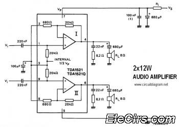
The stereo audio amplifier circuit utilizing the TDA1521/TDA1521Q integrated circuit is designed to offer efficient amplification for audio signals, making it suitable for various audio applications. The TDA1521 is a class AB amplifier, known for its low distortion and high-quality sound reproduction. With an output power rating of 12W per channel, this amplifier is capable of driving standard speakers in home audio systems or smaller public address setups.
The circuit typically requires a power supply voltage ranging from 12V to 28V, which is essential for achieving the specified output power. The integrated circuit incorporates features such as short-circuit protection, thermal shutdown, and a mute function, enhancing the reliability and safety of the amplifier during operation.
In terms of external components, the circuit may include a few resistors and capacitors for stability and filtering purposes. For instance, coupling capacitors are often employed at the input and output stages to block any DC offset, allowing only the AC audio signals to pass through. Feedback resistors can be utilized to set the gain of the amplifier, ensuring the desired amplification level is achieved.
The layout of the circuit should be carefully designed to minimize noise and interference, which can degrade audio quality. Proper grounding techniques and the use of shielded cables for input signals are recommended to maintain the integrity of the audio signal throughout the amplification process.
Overall, the TDA1521/TDA1521Q stereo audio amplifier circuit is an effective solution for providing robust audio amplification in compact designs, making it a popular choice among audio enthusiasts and engineers alike.This is a stereo audio amplifier circuit that provides 12W output power on each audio channel. This simple circuit is built on a single integrated circuit of TDA1521 / TDA1521Q, and only supported by few external components. TDA1521/TDA1521Q.. 🔗 External reference
Related Circuits
This article discusses a new PCB design for a CMoy headphone amplifier. A key feature of this design is that it fits perfectly into a standard Altoids tin can. The new CMoy amplifier includes a bass-boost circuit and a...
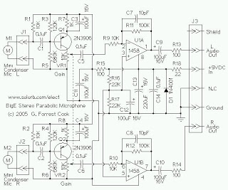
The mini condenser microphone converts sounds into an electrical signal. Resistor R1 provides bias for the condenser microphone's internal amplifier transistor. The 2N3906 PNP transistor acts as a low-noise microphone input amplifier. The 10K gain potentiometer is used for...
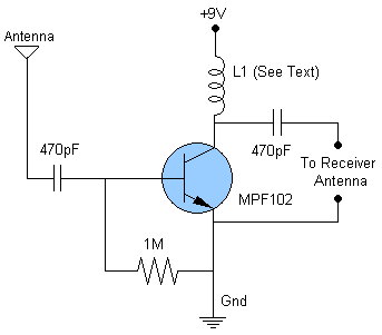
This schematic illustrates an FM, AM/MW, and SW antenna amplifier circuit, also referred to as an antenna preamplifier circuit. It is designed to enhance weak signals from FM, AM/MW, and SW bands. The circuit is straightforward and can be...
Class D audio power amplifier schematic diagram with TDA7480, capable of 10W output power at a load of 8Ω/4Ω and a total harmonic distortion of 10%. Requires a split-supply (max. ±20V). The Class D audio power amplifier utilizing the TDA7480...

Gain increases by decades as the binary input decreases from 1,1 to 0,0. Minimum gain is 1 and maximum gain is 1000. More: Since the switch is static in this type of amplifier, the power dissipation of the switch...
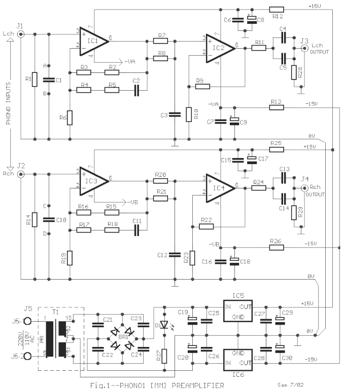
The circuit was designed according to the RIAA implementation of a Hi-Fi phono preamplifier for the purpose of reproducing audio from a moving magnet cartridge. The RIAA (Recording Industry Association of America) equalization curve is essential for the accurate playback...
Warning: include(partials/cookie-banner.php): Failed to open stream: Permission denied in /var/www/html/nextgr/view-circuit.php on line 713
Warning: include(): Failed opening 'partials/cookie-banner.php' for inclusion (include_path='.:/usr/share/php') in /var/www/html/nextgr/view-circuit.php on line 713