
Simplified magnetic amplifier circuitry
The circuit described involves a half-wave magnetic amplifier that initially utilizes a single diode to manage the flow of current through the load coils during the first half of the load voltage cycle. This configuration leads to the generation of load flux, which cancels out due to the opposing nature of the two load coils, thus preventing any impact on the control flux. The absence of current flow during the second half cycle results in no load flux production, effectively eliminating hysteresis losses.
In contrast, a full-wave magnetic amplifier enhances efficiency by employing a bridge rectifier configuration that allows current to flow in one direction throughout the entire load voltage cycle. This configuration ensures that the load current remains unidirectional, thereby circumventing hysteresis losses entirely. The full-wave magnetic amplifier operates with both a.c. and d.c. signals, necessitating a bias winding for optimal performance. This bias winding is crucial for setting the saturable-core reactor at its ideal operating point, allowing for effective control of the load circuit's power.
The block diagram representation of the magnetic amplifier succinctly illustrates the relationship between input and output signals, highlighting the transformation of a low-power a.c. input into a pulsating d.c. output with a significant power gain. The design of magnetic amplifiers can vary, with some configurations allowing for a.c. output directly to the load, thus providing flexibility in application.The power that is used for realignment is a loss as far as the rest of the circuit is concerned. Because of this hysteresis loss in the saturable-core reactor, the power gain is relatively low. A rectifier added to the load circuit will eliminate the hysteresis loss and increase the gain. This is because the rectifier allows current to flow in only one direction through the load coils. A simple half-wave magnetic amplifier is shown in figure 3-38. This is a half-wave magnetic amplifier because it uses a half-wave rectifier. During the first half cycle of the load voltage, the diode conducts and the load windings develop load flux as shown in view (A) by the dashed-line arrows. The load flux from the two load coils cancels and has no effect on the control flux. During the second half cycle, the diode does not conduct and the load coils develop no flux, as shown in view (B).
The load flux never has to reverse direction as it did in the saturable-core reactor, so the hysteresis loss is eliminated. The circuit shown in figure 3-38 is only able to use half of the load voltage (and therefore half the possible load power) since the diode blocks current during half the load-voltage cycle.
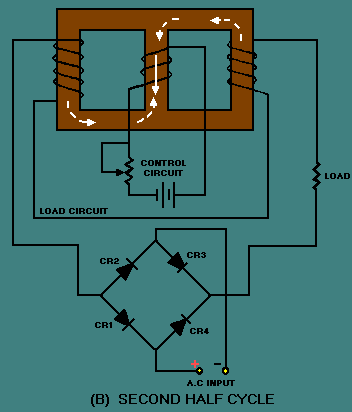
A full-wave rectifier used in place of CR1 would allow current flow during the entire cycle of load voltage while still preventing hysteresis loss. Figure 3-39 shows a simple full-wave magnetic amplifier. The bridge circuit of CR1, CR2, CR3, CR4 allows current to flow in the load circuit during the entire load voltage cycle, but the load current is always in the same direction.
This current flow in one direction prevents hysteresis loss. View (A) shows that during the first half cycle of load voltage, current flows through CR1, the load coils, and CR3. View (B) shows that during the second half cycle, load current flows through CR2, the load coils, and CR4.
Up to this point, the control circuit of the magnetic amplifier has been shown with d. c. applied to it. Magnetic-amplifier control circuits should accept a. c. input signals as well as d. c. input signals. As shown earlier in figure 3-34, a saturable-core reactor has an ideal operating point. Some d. c. must always be applied to bring the saturable core to that operating point. This d. c. is called BIAS. the most effective way to apply bias to the saturable core and also allow a. c. input signals to control the magnetic amplifier is to use a bias winding. A full-wave magnetic amplifier with a bias winding is shown in figure 3-40. In the circuit shown in figure 3-40, the bias circuit is adjusted to set the saturable-core reactor at the ideal operating point. Input signals, represented by the a. c. source symbol, are applied to the control input. The true power of the load circuit is controlled by the control input signal (a. c. ) The block diagram symbol for a magnetic amplifier is shown in figure 3-41. The triangle is the general symbol for an amplifier. The saturable-core reactor symbol in the center of the triangle identifies the amplifier as a magnetic amplifier.
Notice the input and output signals shown. The input signal is a small-amplitude, low-power a. c. signal. The output signal is a pulsating d. c. with an amplitude that varies. This variation is controlled by the input signal and represents a power gain of 1000. Some magnetic amplifiers are designed so a. c. goes through the load rather than pulsating d. c. This is done by placing the load in a different circuit position with 🔗 External reference
Related Circuits
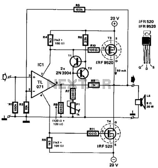
Two complementary MOSFETs are utilized to deliver 20 W into an 8-ohm load. A TL071 operational amplifier serves as the input amplifier. The MOSFETs must be equipped with a heatsink that has a thermal resistance of better than 5...
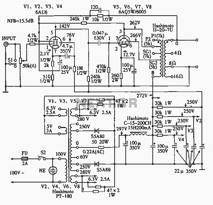
The 6AQ5W / 6005UL four-channel single-ended amplifier circuit is illustrated in the accompanying figure. Only two channels are shown, but it is part of a four-channel system that employs a power transformer for the voltage amplification section. This section...
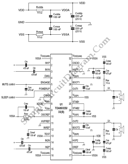
The TDA8932B/33(B) can operate with a symmetrical power supply. In this configuration, three half supply voltage buffers are disabled when powered from a symmetrical source. The TDA8932B/33(B) is a high-efficiency Class D audio amplifier designed for various audio applications. Operating...
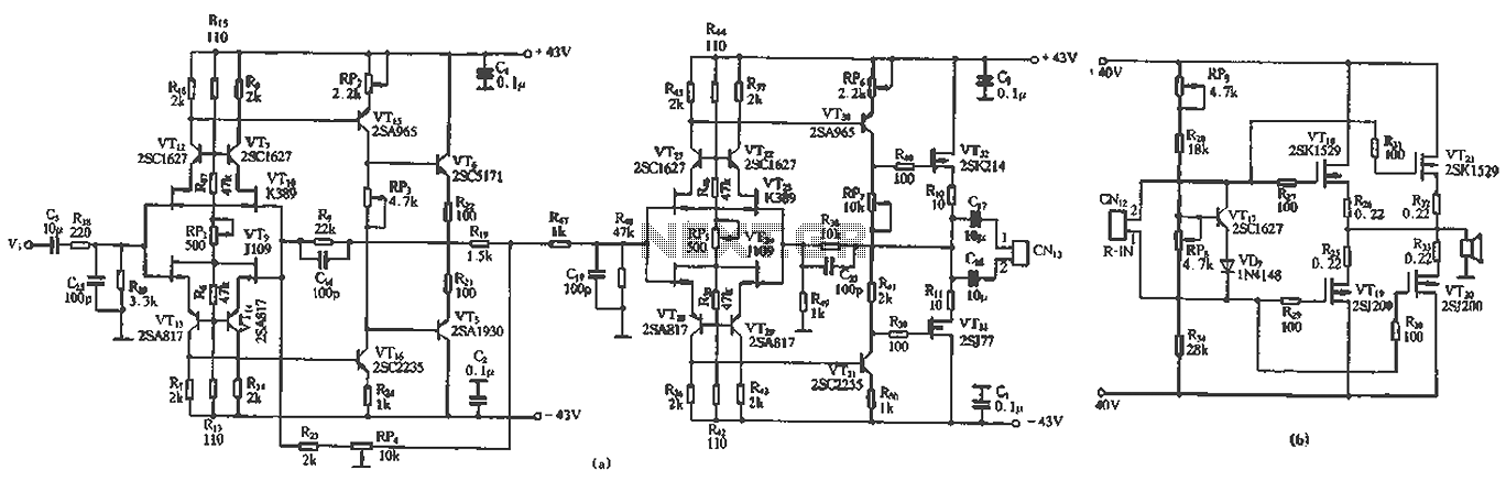
The circuit design features a unique technology and a reasonable structure utilizing all-discrete components with a Class A FET output. The complete circuit includes an input stage, an output stage, and a power level circuit to enhance performance, along...
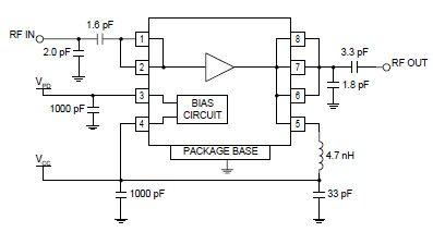
The RF2126 high-power linear amplifier IC, manufactured by RFMD, can be utilized to design a simple yet highly efficient amplifier for 2.45 GHz ISM applications, including WLAN and POS terminals. This component also serves as the final stage in...
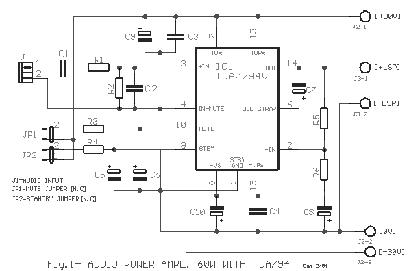
The TDA7294 amplifier module is a monolithic integrated circuit designed for use as a Class AB audio amplifier in high-fidelity applications. It features a wide voltage range and output current capability, allowing it to deliver high power to both...
Warning: include(partials/cookie-banner.php): Failed to open stream: Permission denied in /var/www/html/nextgr/view-circuit.php on line 713
Warning: include(): Failed opening 'partials/cookie-banner.php' for inclusion (include_path='.:/usr/share/php') in /var/www/html/nextgr/view-circuit.php on line 713