
220/440V nameplate on 2-speed motor

The absence of historical context for the NOS lathe presents unique challenges and considerations for potential users. When dealing with a purpose-built lathe, it is essential to understand its design specifications, operational capabilities, and any unique features that differentiate it from standard lathes.
To effectively utilize the lathe, a thorough examination of its components is necessary. Key areas of focus should include the motor specifications, drive system, and control mechanisms. The motor's power rating and torque characteristics will determine the lathe's capacity for various machining tasks. Additionally, understanding the drive system, whether it is belt-driven or direct drive, will provide insights into the lathe's operational efficiency and maintenance requirements.
The control system should also be assessed to determine its ease of use and adaptability. If the lathe incorporates any programmable features or CNC capabilities, familiarity with the software and programming language will be crucial for maximizing its functionality.
In the absence of technical support, it may be beneficial to consult with industry professionals or reference manuals from similar lathes to gain insights into troubleshooting and maintenance practices. Furthermore, documenting any modifications or repairs made to the lathe can provide valuable information for future users or technicians.
Overall, while the lack of history and technical support may pose challenges, a methodical approach to understanding the lathe's design and operational characteristics can lead to successful utilization in various machining applications.I have a NOS lathe with NO history. Period. I think it was maybe purpose-built. In any case, I mention it because there is really no "tech-support.. 🔗 External reference
Related Circuits
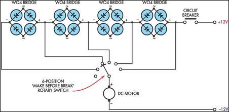
This circuit utilizes the voltage drop across bridge rectifier diodes to create a 5-position variable voltage supply for a DC fan or other small DC motors. While it is not as efficient as a switch-mode circuit, it offers advantages...
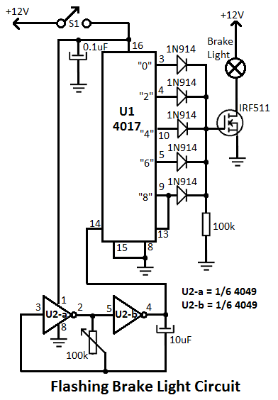
This flashing brake light circuit is designed for motorcycles. When the brake light switch S1 is closed, power is supplied to U1 and U2. The circuit utilizes two inverters from U2. The flashing brake light circuit operates by utilizing a...
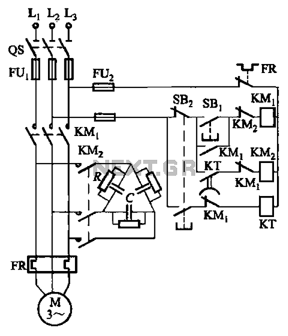
The circuit illustrated in Figure 3-151 consists of capacitor banks arranged in a specific configuration. Figure 3-151 (a) depicts capacitor banks connected in a shaped manner, which is suitable for use with shaped or Y-connected motors. Figure 3-151 (b)...
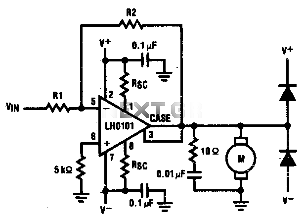
The motor driver amplifier is designed to deliver the rated current to the motor. It is important to manage power dissipation to remain within allowable limits. This precision speed regulation circuit utilizes rate feedback to maintain a constant motor...
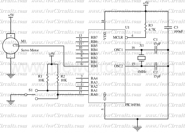
This simple micro-control circuit controls a servo motor according to a 3-state switch. A servo motor acts as an actuator in 3 positions. It has 3 wires, one for VCC, one for Ground, and another one for position control....

Controlling the speed of a three-phase AC motor is achieved by regulating the frequency of the power supply, as the motor operates in synchronization with the line frequency. A three-phase AC motor speed controller functions as a three-phase sine...