
DC Motor Speed Controller
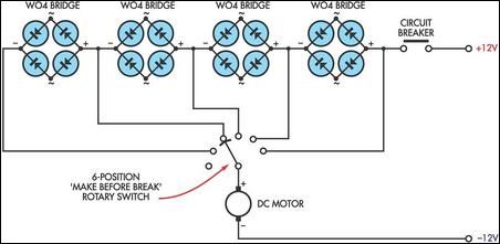
This circuit design employs a series of four bridge rectifiers to achieve variable voltage output. Each bridge rectifier consists of four diodes arranged in a configuration that allows for full-wave rectification, converting AC input into DC output. The parallel arrangement of diode pairs within each bridge rectifier facilitates a consistent voltage drop, which is critical for maintaining the desired output levels across the multiple positions of the rotary switch.
The rotary switch plays a pivotal role in this circuit, allowing for the selection of different voltage levels. The make-before-break design ensures that there is no interruption in the current flow during the switching process, which is essential for preventing voltage spikes that could damage sensitive components. The current rating of the switch must be carefully considered to match the load requirements, as exceeding the switch's capacity can lead to overheating or failure.
For applications requiring higher power, it is advisable to use bridge rectifiers that are rated for greater current loads, as well as a rotary switch or solenoid that can handle the increased demand. The use of solenoids may introduce additional complexity to the circuit but can provide a more robust solution for high-current applications.
To refine the voltage output further, utilizing the common AC inputs of the bridge rectifiers allows for the generation of intermediate voltage steps. This can be particularly useful for applications where precise control over the motor speed is necessary. By adjusting the connections to the AC inputs, the circuit can provide a finer granularity of voltage adjustments, enhancing the overall functionality of the variable voltage supply.
In summary, this circuit offers a practical solution for providing variable voltage to DC motors, balancing simplicity with functionality. Careful consideration of component ratings and configurations will ensure reliable operation across a range of applications.This circuit takes advantage of the voltage drop across bridge rectifier diodes to produce a 5-position variable voltage supply to a DC fan or other small DC motor. It is not as efficient as a switch-mode circuit but it has the virtues of simplicity and no switching hash.
The four full-wave bridges are connected so that each has two pairs of serie s diodes in parallel, giving a voltage drop of about 1. 4V, depending on the load current. The rotary switch should have make before break contacts which should be rated to take currents up to about an amp or so. For higher currents, higher rated bridge rectifiers and a suitably rugged rotary switch (or solenoids) will be required.
If you want smaller voltage steps, you could use the commoned AC inputs on the bridge rectifiers to give intermediate steps on the speed switch. 🔗 External reference
Related Circuits
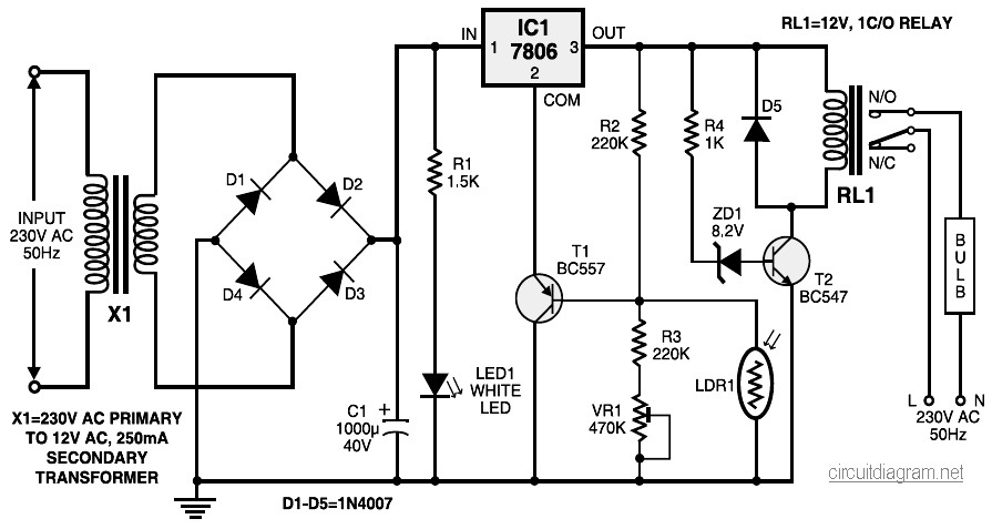
During nighttime, when no light falls on LDR1, it offers a high resistance at the base junction of transistor T1. Consequently, the bias is significantly reduced, and T1 does not conduct. This effectively removes the common terminal of IC1...
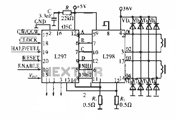
The circuit operates using a dedicated stepping motor controller, the L297. Pin 17 (CW/CCW) is utilized to control the rotation direction of the stepper motor. Pin 18 (CLOCK) regulates the speed of the stepper motor, while pin 19 (HALF/FULL)...

It is a single integrated circuit that includes EEPROM, RAM, an analog-to-digital converter, numerous digital input and output lines, timers, and a UART for RS-232 communication, among other features. A complete programming environment is available for Linux, allowing programming...
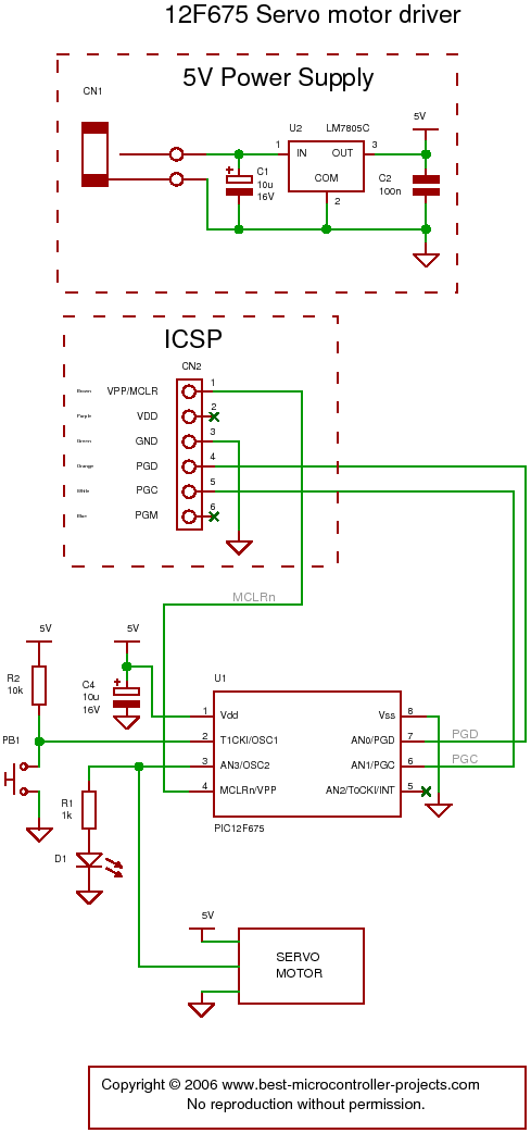
The following circuit illustrates a servo motor driver. This circuit is based on the 12F675 IC. Features include Timer 0 timing and a single control line. The servo motor driver circuit utilizing the 12F675 integrated circuit (IC) is designed to...
Many of today's appliances feature displays and buttons. Instead of relying on motors and gears, numerous household items now incorporate embedded microcontrollers. This exploration focuses on how to experiment with microcontrollers at home. Microcontrollers serve as the central processing units...
The circuit for the solar-powered controller includes a switching circuit, a pulsing circuit, and a high-voltage output circuit. The external power components consist of a 1- to 5-W solar panel and a 12-V motorcycle or camcorder battery. The output...
Warning: include(partials/cookie-banner.php): Failed to open stream: Permission denied in /var/www/html/nextgr/view-circuit.php on line 713
Warning: include(): Failed opening 'partials/cookie-banner.php' for inclusion (include_path='.:/usr/share/php') in /var/www/html/nextgr/view-circuit.php on line 713