
220 volt disco lamp circuit
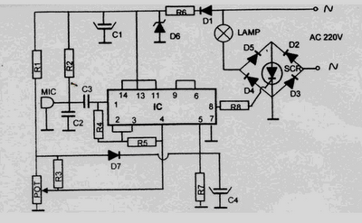
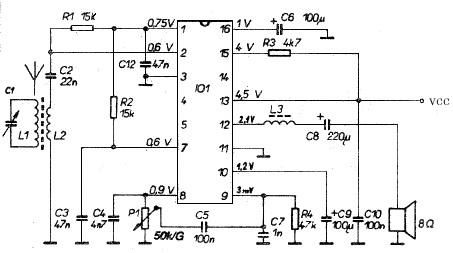
This 220 Volt disco lamp circuit operates by detecting sound levels to trigger lighting effects, making it suitable for use in nightclubs and similar environments. The circuit's primary components include a microphone, which captures sound, and a pre-amplifier stage that enhances the audio signal. The sound signal is processed to determine its amplitude, and when it exceeds a certain threshold, it activates a relay. This relay then controls the power to the disco lamp, allowing for synchronized lighting that responds to the music's intensity.
The choice of microphone is crucial; a microphone coil or a condenser microphone can be employed, depending on the desired sensitivity and frequency response. The circuit's design must ensure that the electrolytic capacitor is adequately rated to handle the voltage, providing stability and reliability during operation. The potentiometer included in the schematic allows for fine-tuning of the gain in the pre-amplification stage. This adjustment is vital to ensure that the circuit can effectively differentiate between ambient noise and the desired sound levels, preventing false triggering of the relay.
In summary, the disco lamp circuit is a straightforward yet effective solution for creating an engaging visual experience that complements musical performances. The integration of sound activation technology with lighting control enhances the atmosphere in entertainment venues, providing an interactive experience for the audience. Proper component selection and circuit design are essential for optimal performance and reliability in various sound environments.This 220 Volt disco lamp circuit is not a voice switch (VOX), because this circuit is too dumb to differentiate between musical sound and human voice. This is more of a voice-activated sound activated. An interesting application is to control the lighting in your disk automatically by the musical sound of high-power amplifier, when the music signa
l is dominating the sound space. Light nightclub circuit schematic diagram is shown below. You can use the microphone coil or condenser microphone for this circuit. Make sure that the electrolytic capacitor is rated for 16 volts or more. The potentiometer is shown in the diagram is used to adjust the gain of the pre-amplification. You can adjust this knob to get a proper sound level of the relay would be activated. 🔗 External reference
Related Circuits

The amplitude of a video signal can be measured using a straightforward circuit that functions as a modified standard peak detector. This device is capable of verifying RGB signals produced by video RAMDACs. U1 is a high-speed buffer, while...
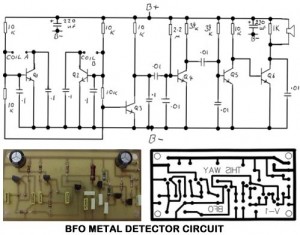
Metal Detector Circuit Overview The metal detector circuit is an electronic circuit that is specifically designed to detect metal that lies deep in the water. The metal detector circuit operates on the principle of electromagnetic induction, where a coil generates...
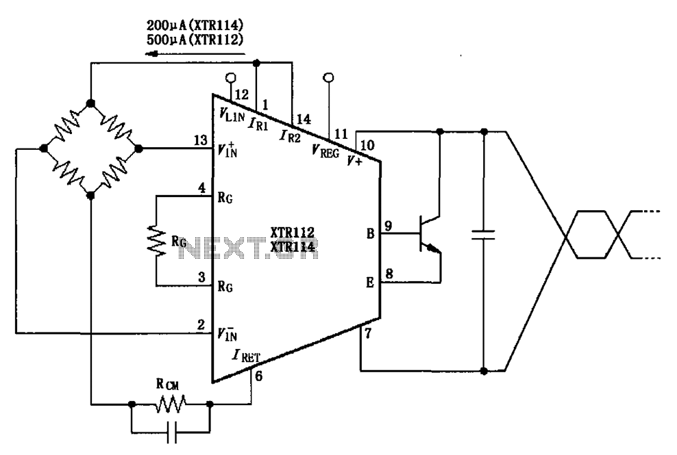
The two current sources within the chip (1 foot and 14 feet out) provide excitation. The output of each current source is 0.2 mA (XTR114) or 0.5 A (XTR112). The common mode input voltage is adjustable, ranging from 1.25...
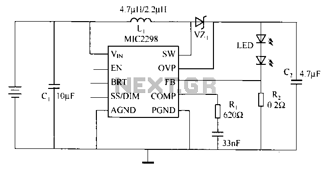
Merry Company (Micrel Inc.) introduced the industry's smallest and most powerful LED driver, the MIC2298, which is widely used in portable electronic devices. The device is a 7W efficient boost DC/DC converter, packaged in a compact 3mm x 3mm...
This AM radio receiver circuit utilizes the TDA1083 radio IC, which is suitable for constructing a simple medium frequency (MF) band radio. The schematic operates within a frequency range of 300 kHz to 3 MHz. The circuit is straightforward...
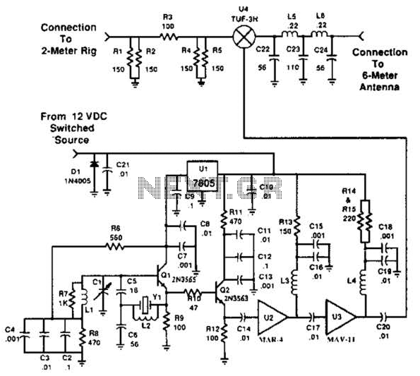
This transverter utilizes the bilateral properties of a balanced mixer to generate a 6-meter output from 2-meter inputs. The component Y1 is a 90-MHz crystal. It is important to note that the input frequency on the 2-meter band is...