
Fast Video Signal Amplitude Measurer Circuit
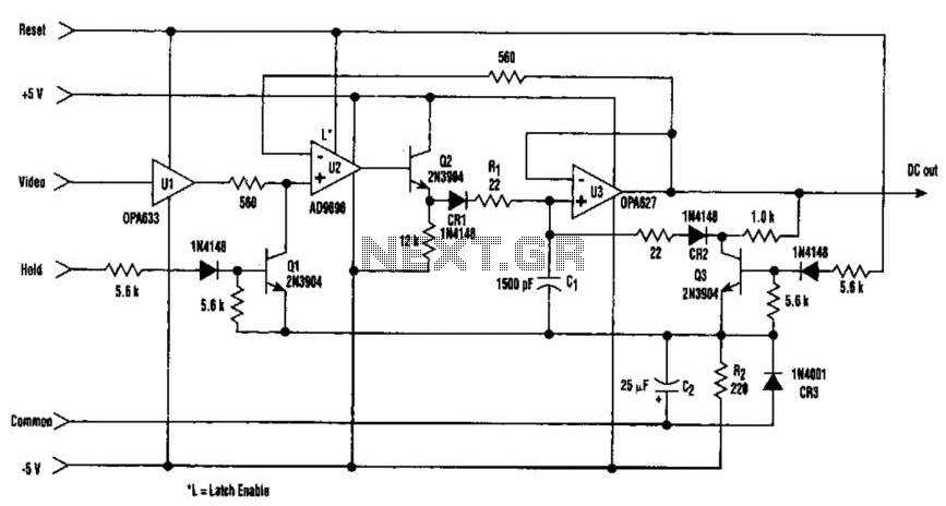
The circuit operates by capturing the peak amplitude of the video signal, which is essential in various applications such as video processing and display calibration. The high-speed buffer (U1) ensures that the incoming video signal is accurately transmitted to the comparator (U2) without significant delay or distortion. This is crucial for maintaining the integrity of the signal being measured.
The latched comparator (U2) compares the incoming signal with a reference level and latches its output state, thus providing a stable reading of the peak amplitude. The hold capacitor (C1) retains the measured voltage, allowing for a consistent output that reflects the maximum amplitude of the video signal over time. This feature is particularly useful when analyzing rapid changes in video signal amplitudes, as it allows for a snapshot of the peak value.
The reset mechanism, controlled by transistor Q3, is vital for ensuring that the system can accurately measure new peaks without interference from previously captured values. During a reset operation, Q3 pulls the comparator output low, clearing the previous state and preparing the circuit for the next measurement cycle.
Overall, this circuit design is effective for applications requiring precise measurement of video signal amplitudes, ensuring reliable performance in various electronic systems that utilize RGB signals from video RAMDACs. Video-signal amplitude can be measured with this simple circuit, which is basically a modified standard peak detector. The device can verify RGB generated by video RAMDACs. Ul is a high-speed buffer and U2 is a latched comparator. CI is a hold capacitor. Reset is performed by Q3. U2 has a latch that maintains the last comparator state. The reset holds the comparator output low during the reset operation. The dc output voltage is equal to the signal`s maximum amplitude. 🔗 External reference
Related Circuits
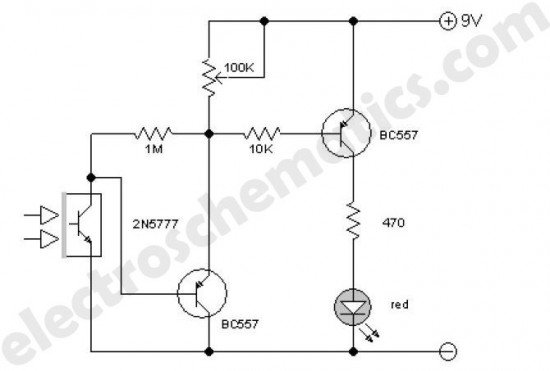
This enhanced infrared detector is designed for use with commercial infrared remote control handsets. This compact circuit is effective for quick go/no-go applications. The infrared detector circuit is engineered to respond to signals emitted by infrared remote control devices, commonly...
An operational amplifier designed for medium power applications, utilized as a headphone amplifier capable of driving low loads. The circuit consists of two amplifiers, with a voltage gain set at 40 dB, determined by the resistor pairs R3-R4 and...
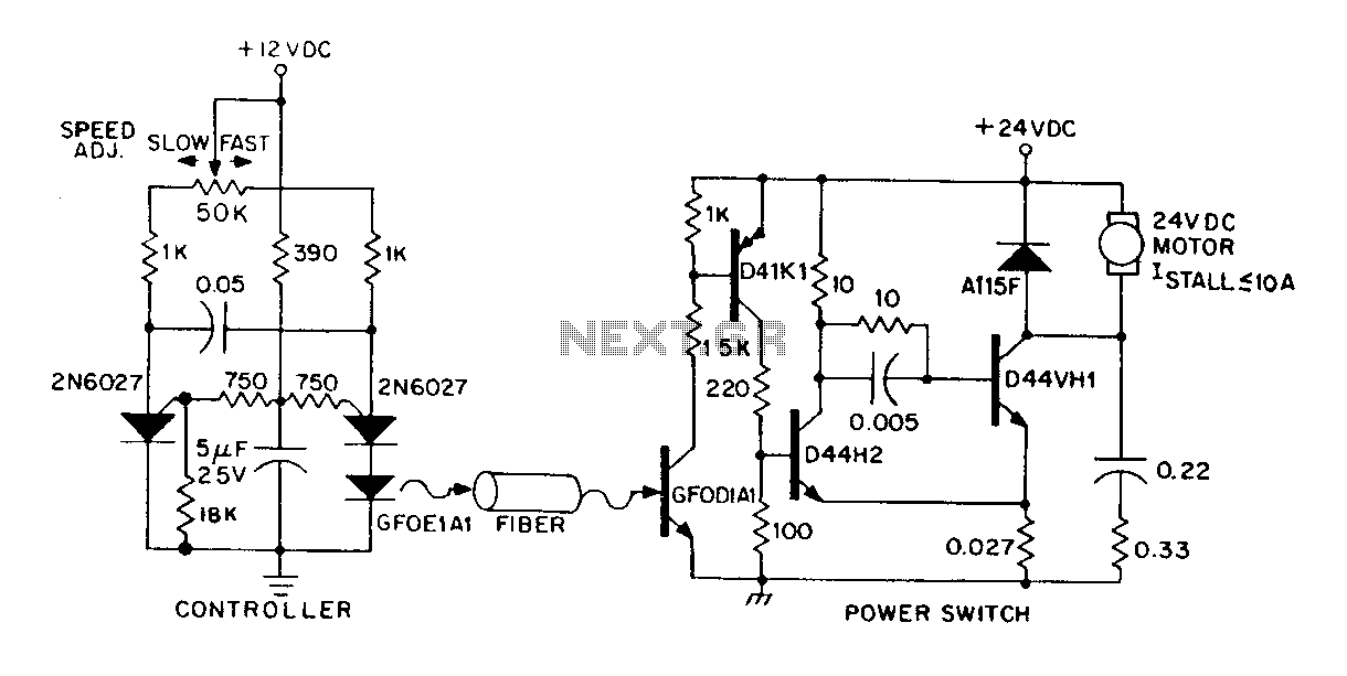
A DC power supply can be controlled through an optical fiber. The circuit includes a small DC motor (1/12 hp) that offers an isolated speed control channel. The control logic operates as an independent module, consuming 300 mW of...
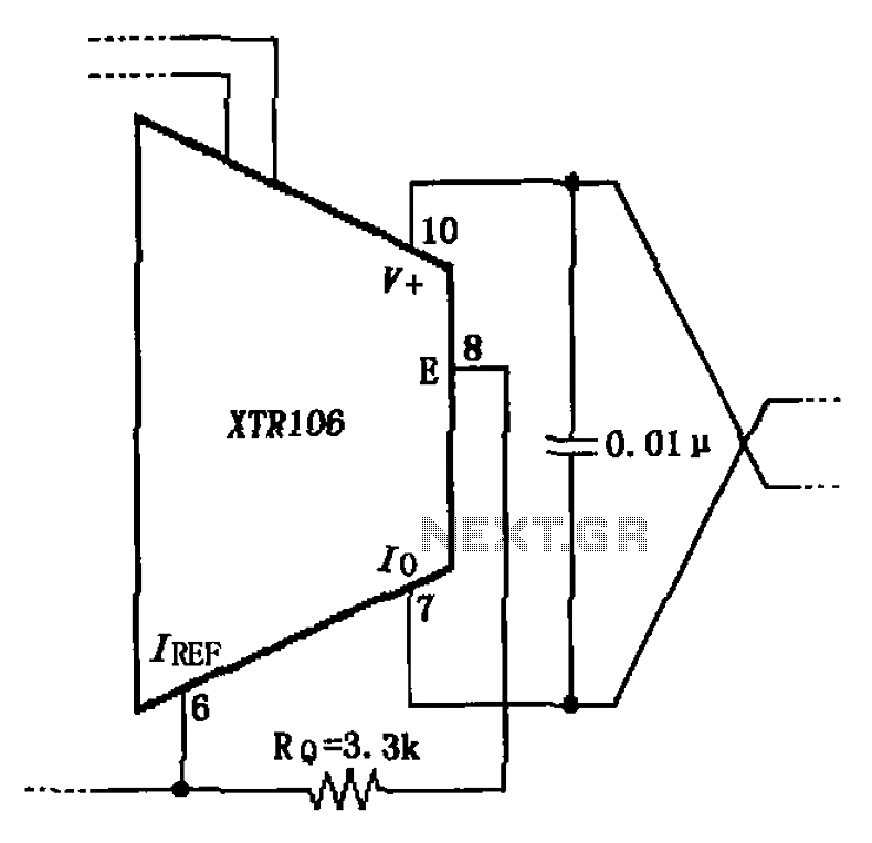
The circuit has been simplified due to the cancellation of an external transistor. The connection between the emitter terminals of the original external transistor and a 3.3k resistor will be removed, as this change has led to a decrease...

The Switchgate is a simple dual gate circuit based on a 556 timer configured in monostable mode, featuring a trigger input that activates two switches. The outputs of the monostables are also available individually. Recent research has led to...

The following circuit illustrates a simple 100W inverter circuit diagram. This circuit is based on the CD4047 integrated circuit (IC). Features include low power CMOS technology. The simple 100W inverter circuit utilizes the CD4047 IC, which is a versatile device...