
20dB VHF AmplifierCircuit Using BF197 Transistor
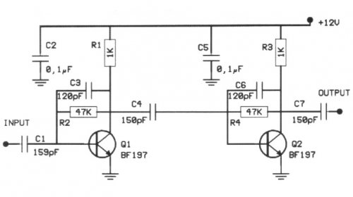
The 20 dB VHF amplifier circuit is designed to amplify very high frequency signals, making it suitable for applications such as radio frequency (RF) communications, television receivers, and other VHF applications. The circuit employs a BF197 transistor, which is a high-frequency N-channel JFET known for its low noise and high gain characteristics.
The circuit typically consists of a few key components: the BF197 transistor, resistors for biasing and load, capacitors for coupling and bypassing, and possibly an inductor for tuning. The input signal is fed into the gate of the BF197 through a coupling capacitor, which blocks any DC component from the signal source. The gate resistor is used to set the bias point of the transistor, ensuring it operates in the active region for optimal amplification.
The output is taken from the drain of the transistor, which is connected to a load resistor. The load resistor determines the gain and output impedance of the amplifier. A bypass capacitor is often placed across the source resistor to enhance the gain at the operating frequency by providing an AC ground at the source terminal.
To maintain stability and prevent oscillations, feedback may be incorporated into the design. This can be achieved by connecting a portion of the output back to the input through a feedback resistor. The amplifier can be tuned for specific frequency responses by adjusting the values of the capacitors and resistors, allowing it to operate effectively within the VHF range.
Overall, this circuit provides a straightforward and efficient solution for amplifying VHF signals, making it a valuable component in various electronic systems requiring signal enhancement.The following circuit shows about 20dB VHF Amplifier Circuit Diagram. This circuit using the BF197 Transistor. Features: simple circuit, with .. 🔗 External reference
Related Circuits
The 1N4001 is a 1 Amp silicon rectifier with a voltage range of 50 to 1000 volts. It features guaranteed high-temperature soldering, high current capability, a diffused junction, low reverse leakage, and utilizes a void-free molded plastic technique for...
One of the simplest methods of metal detection is through a beat frequency oscillator. The circuit consists of two balanced oscillators: one provides a reference signal, while the other acts as the detector element. The frequency of the reference...
A single hand clap will be picked up by the electric mic which is coupled through C1 into the op amp IC1. The output of IC1 triggers the 555 IC timer IC2 which is configured as a monostable multivibrator....
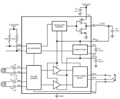
The LM48824's Stereo Headphone Amplifier, utilizing Class G architecture, enhances audio playback time for devices such as MP3 players and mobile TVs. Its adaptive power supply design allows for very low supply rails, effectively doubling power efficiency in comparison...
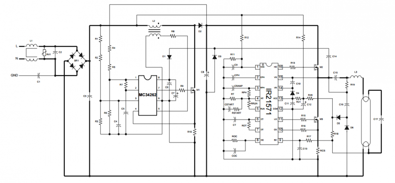
The circuit is built around the IR2520D Ballast Control IC. The IR2520D provides adjustable preheat time, adjustable run frequency to set the lamp power, high starting frequency for soft start and to avoid lamp flash, fault protection for open...
The MAR6 (MSA-0686, 0685, 0885) is a high-performance silicon bipolar Monolithic Microwave Integrated Circuit (MMIC) housed in a cost-effective surface-mount plastic package. This MMIC is designed to function as a general-purpose 50 W gain block. Its applications encompass both...