
1MHz quartz crystal oscillator circuit
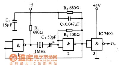
The described oscillator circuit operates at a frequency of 1MHz, leveraging the properties of a quartz crystal resonator to achieve stable oscillations. The quartz crystal functions as a frequency-selective component, providing precise frequency control due to its inherent mechanical resonance characteristics. When integrated into the circuit, the crystal ensures that the oscillation frequency remains consistent and reliable, which is crucial for applications requiring accurate timing signals.
The NAND gate configuration is employed to create a feedback loop necessary for sustaining oscillations. In this setup, the output from the NAND gates is fed back into the circuit, allowing for continuous oscillation generation. The use of NAND gates is advantageous due to their versatility and the ability to implement various logic functions within the same circuit.
NAND gate 3 serves as the output buffer stage, providing a clean and robust signal that can drive other components or circuits without significant loading effects. This buffering is essential to maintain signal integrity, particularly when the generated frequency signal is interfaced with other electronic systems.
In practical applications, this 1MHz quartz crystal oscillator circuit can be utilized in various fields such as telecommunications, signal processing, and frequency calibration for precision instruments. The design's simplicity and effectiveness make it an ideal choice for generating stable clock signals in digital circuits and microcontroller applications.The oscillator circuit which is composed of the 1MHz quartz crystal resonator and the NAND gate is as shown in the figure, the NAND gate 3 is the output buffer stage. This circuit can be used to calibrate the standard frequency. Figure 1 The 1MHz quartz crystal oscillator circuit.. 🔗 External reference
Related Circuits
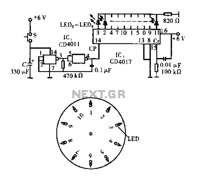
Dot Award. This circuit is tested and functional. The circuit consists of two integrated circuits (ICs). IC1 serves as a pulse source, activated by a momentary button switch (S). When the button is pressed, it charges capacitor C1, which...

An RF power amplifier is an electronic amplifier used to convert a low-power radio-frequency signal into a larger signal of significant power, typically for driving the antenna of a transmitter. It is optimized for high efficiency, high output power...

The circuit presented is designed to prevent burning one's tongue by monitoring the temperature of coffee. It consists of a voltage regulator, a temperature-to-voltage converter, a comparator, and two LEDs. In general, the circuit operates as follows: if the...
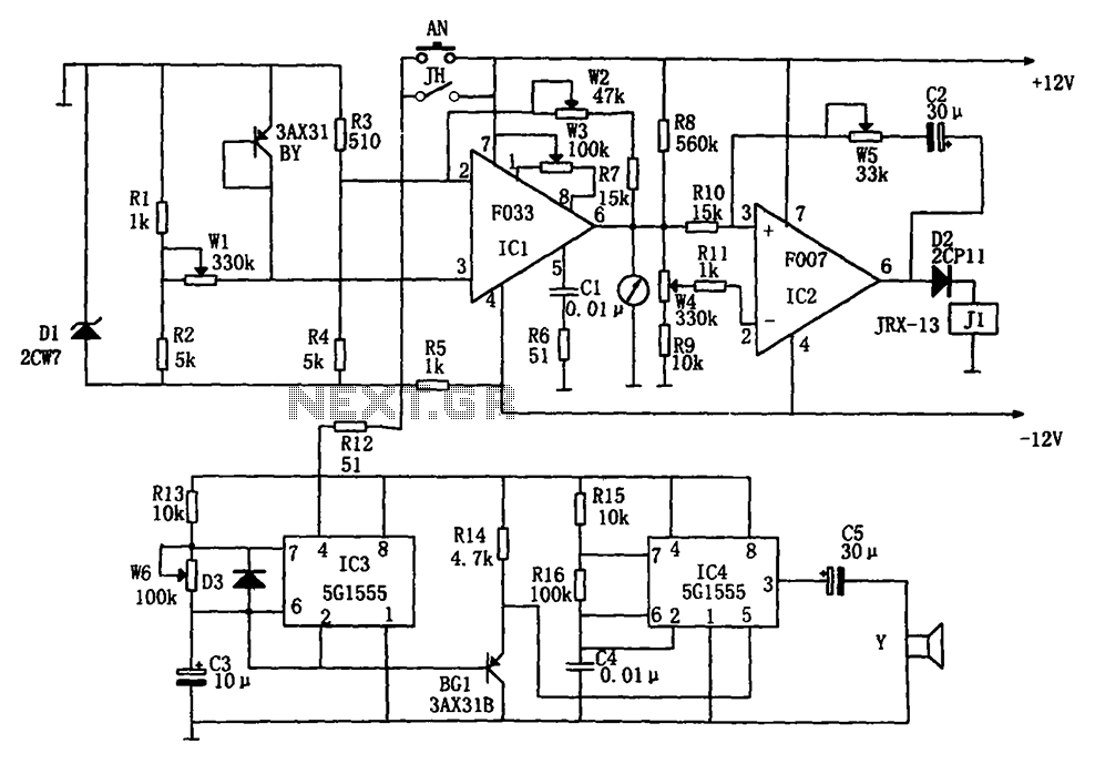
The temperature alarm circuit shown in the figure consists of an inverting amplifier (IC1), a comparison amplifier (IC2), a low-frequency multivibrator (IC3), a controllable oscillation frequency multivibrator (IC4), a bridge measurement network, a speaker (Y), and a power supply...
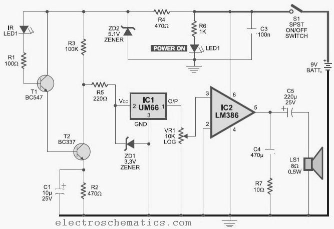
This infrared detector is capable of detecting the presence of modulated infrared signals in its vicinity from various electronic sources, such as an IR handheld remote. The infrared detector operates by utilizing a photodetector that is sensitive to infrared light....
This circuit is a melody generator circuit diagram controlled by the UM66 IC. The UM66 is a CMOS IC designed for applications such as call bells, telephones, and toys. It features a built-in ROM programmed to play music and...
Warning: include(partials/cookie-banner.php): Failed to open stream: Permission denied in /var/www/html/nextgr/view-circuit.php on line 713
Warning: include(): Failed opening 'partials/cookie-banner.php' for inclusion (include_path='.:/usr/share/php') in /var/www/html/nextgr/view-circuit.php on line 713