
Power-Off Time Delay Relay
The described circuits utilize a relay mechanism to control the disconnection of a load after a specified delay. When the ignition or light switch is turned off, the capacitor begins to charge through a resistor connected to the power supply. This charging process allows the relay to remain in a closed state, thereby maintaining the connection of the load.
As the capacitor charges, the voltage across it increases. The diode is positioned in such a manner that it allows current to flow into the capacitor while preventing it from discharging back into the circuit. When the voltage at the anode of the diode reaches 12 volts, it triggers the relay to open, disconnecting the load. This delay in opening the relay contact can be adjusted by changing the resistor and capacitor values, allowing for customization based on the specific requirements of the application.
The relay used in this circuit should be rated appropriately for the load it will control, ensuring safe operation. Additionally, the capacitor must have a voltage rating higher than 12 volts to prevent breakdown during operation. The circuit can be further enhanced by incorporating additional components such as a Zener diode for voltage regulation or a transistor for improved switching performance. Overall, this configuration provides a reliable method to control electrical loads with a timed delay, enhancing the functionality of automotive and lighting systems.The two circuits illustrate opening a relay contact a short time after the ignition or ligh switch is turned off. The capacitor is charged and the relay is closed when the voltage at the diode anode rises to 12 volts
🔗 External reference
Related Circuits
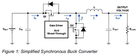
Increased Flexibility for Low-Power Synchronous Buck Converters. Contemporary synchronous buck converters designed for portable applications offer a power-save mode operation to sustain high efficiency throughout the entire range of operation. Modern low-power synchronous buck converters are essential components in portable...
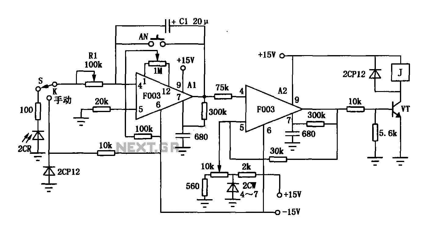
The F003 circuit is a versatile photographic component that functions as an operational amplifier amplifying automatic timer circuit. The operational amplifier A1 serves as an integrator, while operational amplifier A2 is configured as a comparator. A 2CR silicon photocell...
This schematic represents a simple water or liquid level sensor relay switch circuit, designed to control electronic appliances based on water levels. The circuit is particularly useful for automatically turning off a water pump when a water tank, pool,...
The project originated from a request by Tony Bowler, a member of the Long Eaton Club, who sought assistance in converting a "Golden Oldie" model to electric free-flight. He selected Vic Smeed's "Debutante" to be powered by seven AE...
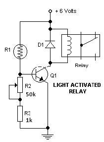
This light-dark switch activated relay circuit schematic represents one of the simplest electronic circuits designed to activate other electronic devices based on light or darkness. It requires a single electronic relay and a few common components that are not...
Once the mains power supply is interrupted, the relay will only activate after a delay of 150 to 210 seconds, depending on the tolerance of the RC circuit. The described circuit operates as a time delay relay system, which is...