
Hi Fi Amplifier circuit
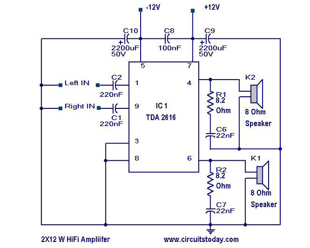
The TDA 2616 is a high-performance integrated circuit designed for use in audio amplification applications. It is particularly valued for its efficiency and sound quality, making it suitable for various consumer electronics, including radios, tape players, and televisions. The circuit typically includes a power supply section, input stage, and output stage, which work together to amplify audio signals.
The power supply section of the amplifier circuit usually requires a dual power supply, providing both positive and negative voltages to the TDA 2616. The recommended voltage range is typically between ±12V to ±18V, ensuring optimal performance without distortion. Capacitors are used to filter the power supply to eliminate noise and ensure stable operation.
The input stage of the amplifier circuit receives audio signals from various sources. It may include coupling capacitors to block DC components while allowing AC audio signals to pass through. Additionally, resistors may be used to set the input impedance, ensuring compatibility with different audio sources.
In the output stage, the TDA 2616 drives the speakers directly. The output stage is designed to handle the power requirements, delivering 12 watts per channel into an 8-ohm load. This is achieved through appropriate heat sinking to dissipate heat generated during operation, as the amplifier can run hot under heavy load conditions.
Feedback resistors may be included in the circuit to stabilize gain and improve linearity, resulting in lower distortion levels. Bypass capacitors are often placed near the power pins of the IC to enhance stability and transient response.
Overall, the TDA 2616 amplifier circuit is a robust solution for audio amplification, providing excellent sound quality and power output suitable for a variety of audio applications. Proper attention to component selection and layout will ensure optimal performance and reliability in the final product.A simple Hi Fi amplifier circuit diagram with schematic for making audio amplifier,design using TDA 2616 IC, which is a stereo power amplifier, useful for radio,tape and television. Delivers 2*12 watts net 24 watts. 🔗 External reference
Related Circuits
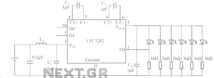
The LTC3202 is a device from Linear Technology that eliminates the need for a charge pump gated oscillator. It is designed as a charge pump for driving white LEDs powered by a lithium-ion battery. To address noise issues, the...
The circuit is based on a simple inductor-capacitor filter circuit, and needs only a pot and a small light bulb to set and stabilise the oscillation. The frequency is fixed, and with a good inductor should be capable of...
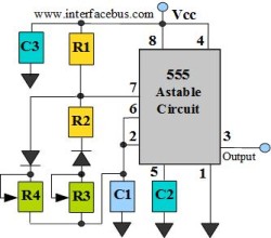
The astable multivibrator circuit lacks a stable state. In the absence of an external signal, the internal transistors alternately switch between cutoff and saturation at a frequency determined by the RC time constants of the coupling circuits. Therefore, an...
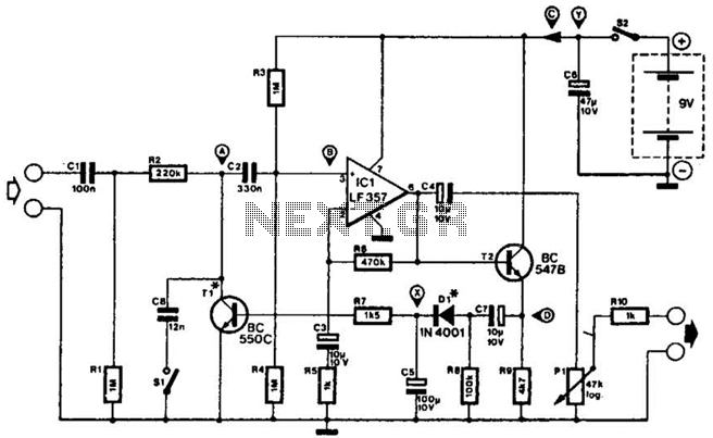
This compressor will compress a 25-mV peak-to-peak (p-p) audio signal to a 20-V p-p output, maintaining input levels between 1.5 V p-p and 3.5 V p-p, with a frequency response ranging from 7 Hz to 67 kHz. It is...
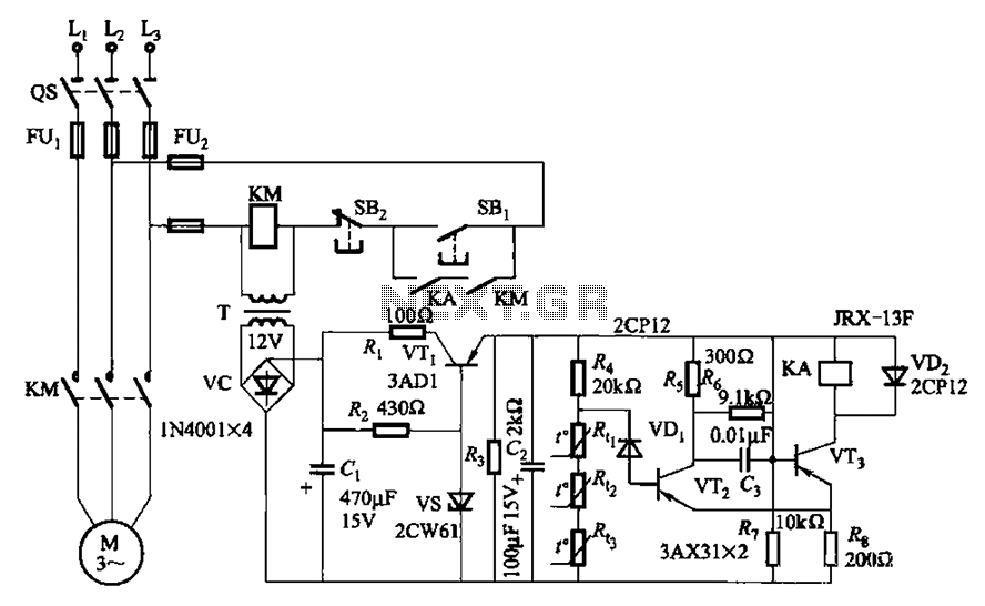
A P-type transistor (VT2, VT3) and other components form a common emitter-coupled trigger, functioning as a Schmitt trigger device. This setup serves as a switching circuit to detect changes in the resistance of a PTC thermistor, thereby controlling the...
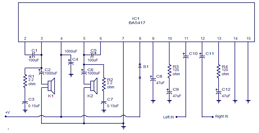
The BA5417 is a stereo amplifier integrated circuit (IC) that features several advantageous characteristics, including thermal shutdown, a standby function, soft clipping, and a wide operating voltage range. It can deliver 5 watts per channel into 4-ohm loudspeakers when...